Transcription of Simpson Model 260 Volt-Ohm-Milliammeter
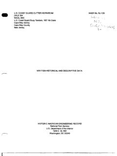
1 PANEL METERS by MODELS 27, 37, 47, 57 3~" RECTANGULAR ACCUR ACY : 2~ SC AL E LENGT H: 2-9/16" III' 11'1 " II' " 'II III ,.(1 \ , .. \ 'I' I' ~~:.'~ ~,~, ~ ~ --~'-_II. '7. MODELS 25,35, 45, 55 Simpson MODERNISTIC 3!" ROUND. ACC URAC Y 2~ CLEAR VUE SC ALE LENGT H: 1-7/8" ALSO AS MODELS 125, 135 BUILT TO SPECIAL ORDER 145 AND 155 - ALL 2!"2P. 3P. It!". 5!" SIZES ROUND . SC ALE 1-7/8 " MODELS 27, ILLUMINATE D 3!" RECTANGULAR ACCURACY: 2$ SCALE LE NG TH: 1-5/ 16" ~ r~1 ,~ 7 iiiiiiiii ~ ( I!!I!li MODELS 127, 137, 147, MODELS 29,39,49,59 157. 2!" RECT ANGULAR It!" RECTANGULAR ACCUR ACY : 2$ ACCUR ACY : 2$ SC ALE LENGTH: 3-29/32" SCALE LENGTH: 1-7/8" NEAR L Y 800 DIFFERENT S I ZES AND KINDS OF S IMPSON PANEL METERS ARE AVAILABLE FRO M YOUR ELE CTRONIC PART S JOBBER. WHETHER YOU NEED ONE PANEL METE R OR A DOZEN LOOK FOR THE FAMI LIAR OR AN GE COLORED S IMPSO N BOX . FOR FURTHER INFORMATION WRITE Simpson ELECTRIC CO 5200 W. K INZ I E ST CHI CAGO Itlt.))
2 ILL ESTEBROOK 9-1121. -~ OPERATOR'S MANUAL VOI.,..oHM-MlLLIAMME'I'ER Model 260 Simpson ELECTRIC COMPANY 5200 W. KINZIE ST., CHICAGO 44, ILLINOIS. EStabrook IN CANADA, BACH Simpson , LTD., LON DOH, ONTARIO Copyright 1955. Simpson Electric Co. Printed in TABLE OF CONTENTS SECTION III FUNCTIONING OF PARTS Schematic Diagram .. Volcmeter Circuit -20,000 Ohms Per Volt. Resistance of Multiplier Resistors .. Voltmeter Circuit -1000 Ohms Per Volt. Rectified by Copper Oxide Rectifier. Output Meter .. Reading Voltage Effective Resistance. Volt Range .. Volume Level Meter. Conversion of Scale. Output Meter .. Ohmmeter .. Milliammeter and Ammeter. SECTION IV MAINTENANCE Do Not Drop Your 260 .. Make Proper Settings Before Use .. Battery Replacement .. Pointer Won't Zero on Rx1 and RxlOO Ranges. Pointer Won't Zero on Rx10,000 Range. How to Replace Batceries. Parts List .. SECTION V Model 260 SPECIFIC APPLICATIONS General.. Measuring Grid Currents.
3 F .M. Alignment .. Diode Circuits. High Mu Plate Voltage. 20 20 20 21 21 22 22 23 23 23 24 24 24 25 27 27 27 28 28 28 32 34 34 34 34 35 T ABLE OF CONTENTS Bias of Power Detector .. Model 260 as a Condenser Tester. Initial Deflection Not Present .. Positive Jack to Positive Condenser Terminal Should Read About. 5 Megohm .. Paper Condensers .. Condensers From .001 Mfd. to Mfd. Descriptive Tables .. SECTION VI SUPPLEMENTARY DATA RMA Resistor Color Code Chart .. RMA Mica Capacitor Color Code Chart. RMA Condenser Marking Code .. Volts-Decibels Conversion Table. Capacitive Reactances. Audio Frequencies. Radio Frequencies .. 35 35 35 36 36 36 37 38 39 40 41 42 44 44 44 ') 4 Fig. 1 Fig. 2 Fig. 3 Fig. 4 Fig. 5 Fig. 6 Fig. 7 Fig. Sa Fig. 8b Fig. 9 Fig. lOa Fig. lOb Fig. 11 Fig. 12 Fig. 13 6 LIST OF ILLUSTRATIONS Simpson Volt-Ohm-Milliammeter Model 260 Simplified Volcmeter Circuit. Simplified Voltmeter Circuit.
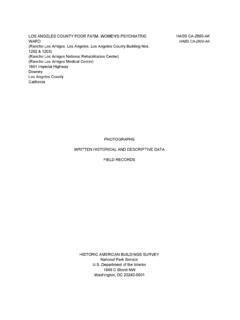
4 Simplified Output Meter Ohmmeter Circuit with Selector Switch in Position Rx 1 .. Ohmmeter Circuit with Selector Switch in Position Rx 100 .. Ohmmeter Circuit with Selector Switch in Position RxlO,OOO .. Simplified Microammeter Circuit .. Simplified Milliammeter and Ammeter Circuit.. Model 260 Schematic Model 260 Parts Layout -Rear Model 260 Parts Layout -Rear View of Front Panel .. Model 260 Used as Condenser RMA Resistor Color Code Chart .. RMA Mica Capacitor Color Code Chart .. PAGE 2 21 22 23 24 25 25 26 26 29 30 31 37 39 40 f oJWW-oJUI WORLD FAMOUS As the purchaser of a Simpson 260, you are now the owner of the most famous testing instrument in the world. Com pact, of unusually high sensitivity (50 microamperes full scale), the Model 260 has earned its top ranking reputation as the result of quality construction joined to exceptional engineering versatility. This engineering superiority is, in turn, the product of invaluable years of experience with every single unit comprising the complete assembly.
5 In choosing the Simpson 260, you have concurred in the verdict of over 300 governme nt agencies and university laboratories which, long before World War II, and all through it, purchased it. in quantities un equalled by any competitive instrument. Ie served on every batdefront and in every branch of our armed services. MANY FEATURES IN "260" In no other instrument of its kind do you find features such as are contained in the Simpson Model 260. Ics trim, scien tific appearance --the 4];i" modernistic instrument, the heavy bakelite case, the neat bakelite .panel --gives evi dence of inner quality. These hidden features are too nu merous to mention here, but your pride in your new instru ment will grow as you learn of them. Parts are assembled and placed in position so they cannot become loose or detached from their original positions. All the sub-assem blies are mounted on specially designed bakelite panels, or on a specially designed sub-panel, made and engineered expressly for a specific function in the Model 260.
6 7 Simpson BUILDS ITS OWN TEST EQUIPMENT When you purchase Simpson test equipmenr, you get equip menr made almost enrirely within the various planrs of our Company. Each component pan of the 260 has been de signed and completely rooled and manufactured in our own planrs, with the exception of the resistors and one or two other functionally less important parts. The Model 260, like all other Simpson testers, is not an assembly job made up from purchased pans such as is true of the majority of testers offered on the market. We are by far more self-conrained than any other manufac turer of test equipmenr. This is your assurance that the testers we offer will not quickly become obsolete . Our tremendous investmenr in expensive production rools is your safeguard against obsolescence and further assurance of unvarying quality. Here at Simpson we do not think of making instrumenrs merely to sell. We think of making instrumenrs ro serve. Our inrerest in your Model 260 and in your satisfaction with it never ceases.
7 That is the reason for this Operator's Manual. We want you to know how to get the most from your 260. The Model 260 is a rugged instrumenr and will withstand a great deal of abuse. We urge you, however, to treat it with care as its mechanism is actually more delicate than that of a watch. If you will keep it clean, free from conrinuous severe vibration and avoid dropping it, your Model 260 will give you a lifetime of accurate, dependable service. OPERATOR'S MANUAL Simpson Model 260 YOLT OHM MILLIAMMETER SECTION I GENERAL DESCRIPTION The Simpson Volr-Ohm-Milliammeter Model 260 offers the service dealer a small, compact and complete instrument with high sensitivity for testing and locating trouble in all types of circuits. The large four and one-half inch meter provides a long scale that is easy to read, and the compact arrangemenr of the conrrols allows the overall size of the bakelite housing ro be comparatively small for maximum portability. Each unit is supplied with an operator's manual and one set of red and black test leads with insulated clips.
8 The electrical circuit is designed to give maximum insur ance against inaccuracy and damage to the componenr pans. Highly accurate carbofilm resistors are used ro in sure long life and dependability, and these are firmly held in place in a special bakelite housing designed for this purpose. The entire assembly is truly rugged and can well withstand the wear and tear of the service work for which it is designed. ACCURACY Accuracy is 3% and 5% of full scale deflection. 8 9 GENERAL DESCRIPTION MEASUREMENT RANGES D. C. VOLT AGE voles 0-10 voles 0-50 voles 0-250 voles 20,000 ohms per vole sensieiviey o -1000 vole s 0-5000 voles A. C. VOLTAGE voles 0-10 voles 0-50 voles 1,000 ohms per vole sensieiviey0-250 voles 0-1000 voles 0-5000 voles A. F. OUTPUT VOLTAGE voles 0-10 voles 0-50 voles Mfd. internal series condenser 0-250 volts 0-1000 voles VOLUME LEVEL IN DECIBELS -12 co + 3 decibels oco +15 decibels Calibrated for reference level+14 to +29 decibels of 500 ohms and.
9 006 Wacts+28 co +43 decibels +40 to +55 decibels 10 GENERAL DESCRIPTION D. C. RESISTANCE 0-2000 ohms (12 ohms cencer) 0-200,000 ohms (1200 ohms cencer) 0-20 megohms (120,000 ohms cencer) CURRENT IN D. C CI RCUITS 100 microamperes 10 milliamperes 100 milliamperes 250 millivoles 500 mi lliamperes 10 amperes D. C. VOLT AGE MEAS UREME NTS D. C. voleage is measured by applying ehe unknown volcage co ehe meeer ehrough suieable ineernal series resiseors. The meeer has a full scale sensieiviey of 50 microamperes ae 100 millivolcs wieh an incernal resiseance of 2,000 ohms, giving ehe inserumenc an overall sensieiviey of 20,000 ohms per vole. A. C. VOLTAGE MEASUREMENTS A. C. voleage measuremencs, including oueput and decibel readings, are made possible by ehe use of an incernal cop per oxide receifier conneceed in series wieh ehe meeer. A precision wound incernal shunt resiseor is conneceed in parallel wieh ehe meeer in order co obeain a sensieiviey of 1,000 ohms per vole. D.
10 C. RESISTANCE MEASUREMENTS D. C. resiseance measuremencs are made by employing an ineernal bactery and precision series and shune resistors, resulcing in accuraee indicaeion of resiseance values. 11 GENERAL DESCRIPTION CURRENT MEASUREMENTS IN D. C. CIRCUITS Current is measured through the use of preClslOn internal shunts resulting in accurate indication throughout the varIOUS ranges. SECTION II OPERATION CAUTION When making measurements, turn off the power to the circuit under test, clip the test leads to the desired points and then turn on the power to take the reading. Turn off the power before you disconnec t the meter. ZERO ADJUSTMENT Before taking readings, be sure that the pointer is on zero. If pointer is off zero, adjust by mli!ans of the slotted screw located in the bakelite case directly below the meter scale as shown in Figure 1. Use a small screw-driver to turn this adjustment slowly to the right or left until the pointer is directly over the zero point on the scale.