Transcription of Simrit Technical Manual 2007: General Technical …
1 Freudenberg Simrit GmbH & Co. KG | Technical Manual 2007897 Technical Principles| General Technical data and MaterialsTechnical PrinciplesGeneral Technical data 898 Materials Basics Concepts 906 Testing and Interpretation Test Results 912 General material Descriptions 925 Suggestion for Storage 970 Summary of the Mentioned Standards 971 General Technical data and Materials Freudenberg Simrit GmbH & Co. KG | Technical Manual 2007898 Technical Principles | General Technical data and MaterialsGeneral Technical DataISO Tolerances, Selection in m Nominal dimension range [mm] Piston guidesGroove base for two-piece piston sealsGroove base for piston sealsSimmerring shaft piston rodsSimmerring (housing), rod guides, wiper hous-ingGroove base for rod sealsSimmerring housing, special casesCylinder bores over toh8h9h10h11f7f8e8H8H9H10H11f81.
2 6 3 0000 6 6 1414 25406020 14 25 40 60 16 20 280000636 0000 10 10 2018 30487528610 0000 13 13 2522 36589035 22 36 58 90 28 35 4700001310140000 16 16 32274370110431418 27 43 70 110 34 43 5900001618240000 20 20 40335284130532430 33 52 84 130 41 53 7300002030400000 25 25 503962100160644050 39 62 100 160 50 64 8900002550650000 30 30 604674120190766580 46 74 120 190 60 76 106000030801000000 36 36 72548714022090100120 54 87 140 220 71 90 1260000361201400000 43 43 8563100160250106140160 63 100 160 250 83 106 1480000431601801802000000 50 50 10072115185290122200225 72 115 185 290 96 122 1720000502252502502800000 56 56 11081130210320137280315 81 130 210 320 108 137 191000056 Freudenberg Simrit GmbH & Co. KG | Technical Manual 2007899 Technical Principles | General Technical data and MaterialsNominal dimension range [mm] Piston guidesGroove base for two-piece piston sealsGroove base for piston sealsSimmerring shaft piston rodsSimmerring (housing), rod guides, wiper hous-ingGroove base for rod sealsSimmerring housing, special casesCylinder bores over toh8h9h10h11f7f8e8H8H9H10H11f83153550000 62 62 12589140230360151355400 89 140 230 360 119 151 214000062 4004500000 68 68 13597155250400165450500 97 155 250 400 131 165 232000068 Tbl.
3 1 Selection of ISO dimensions Production tolerances In the following chapter on materials will consider the technological quality of the highly elastic materials from Simrit , elastomers and plastomers as well as their ap-plications with reference to their physical and chemical properties. However, the dimensional accuracies achievable on the finished part with the above mentioned materials are also important. Designers and users very frequently aim for tolerance standards used for metal parts in me-chanical engineering when they consider the tolerances required and the rules governing tolerances. However, narrow tolerances are generally not possible during the manufacture of sealing components and parts made of highly elastic materials. The tolerances specified in DIN 7715 are generally applicable for sealing components and parts made of highly elastic materials, and assuming that there are no special requirements for specific products tolerance level M3 is considered applicable.
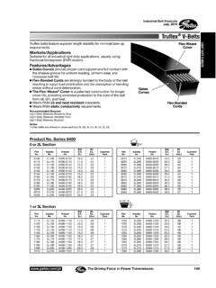
4 Deviations from the values specified in DIN 7715 must be agreed in consultation between user and manufac-turer. Permissible deviations for soft rubber parts(extract from DIN 7715 Part 2 )Dimension terms A differentiation is to be made between two kinds of permissible dimensional deviations F and C for all moulded parts within the tolerance classes . F: Deviations dimensions related to the mould. Dimen-sions that are not influenced by factors that affect shape such as compression and lateral offset be-tween different moulded parts (high and low part, cores). See dimensions w, x and y in Fig. 1 . C: Deviations in dimensions related to the mould clos-ing. Dimensions that may be changed by changes in the density of the compression and the lateral offset between different moulded parts.
5 See dimensions s, t, u and z in Fig. 1 . xszuywtUpper part of mouldDirection of pressureFlashLower part of mouldMoulded part Fig. 1 Mould and moulded part Freudenberg Simrit GmbH & Co. KG | Technical Manual 2007900 Technical Principles | General Technical data and MaterialsNominal dimension range [mm]Class M 1 Class M 2 Class M 3 Class M 4F c F c F c F c overtoPermissible deviations of dimensions in mm6,30,100,100,150,200,250,400,500,506,3 10,00,100,150,200,200,300,500,700,7010,0 16,00,150,200,200,250,400,600,800,8016,0 25,00,200,200,250,350,500,801,001,0025,0 40,00,200,250,350,400,601,001,301,3040,0 63,00,250,350,400,500,801,301,601,6063,0 100,00,350,400,500,701,001,602,002,00100 ,0 160,00,400,500,700,801,302,002,502,50 Permissible deviations in %1600,30*)0,50*)0,80*)1,501,50*) Values only on agreementTbl.
6 2 Extract from DIN 7715 Regardless of the values given in the tables, product-related tolerances are shown in: DIN 3760 for rotary shaft seals DIN ISO 3302-1 accuracy level M2 for diameter ranges of moulded diaphragmswithout fabric reinforcement DIN ISO 3302-1 accuracy level M3 for diameter ranges of moulded diaphragmswith fabric reinforcement and/or metal insert. DIN 16901, Part 2 for manufactured parts made of injection moulded thermoplastics DIN 7168 for machined parts made of PTFE or other thermoplastics If tolerances must be less than in DIN 7168 for func-tional reasons, the "reduced material tolerances" given in Tbl. 3 must be maintained. In exceptional cases consultation with us is recommended. Nominal dimension range [mm] Tolerance according to DIN 7168 average Reduced working tolerances range overto 6 0,1 0,10 6 30 0,2 0,15 30 65 0,3 0,20 65 120 0,3 0,30 120 200 0,5 0,40 Tbl.
7 3 Extract from DIN 7168 Freudenberg Simrit GmbH & Co. KG | Technical Manual 2007901 Technical Principles | General Technical data and MaterialsNominal dimension range [mm]Pressed, bored and stamped partsFlange thickness of pressed partsCut-outs and parts cut with a templateBatch vulcanised partsHoses and discs cut from hoseDiameterProfile in cross-sectionand by the metreOutside groundOutside not groundInside diameterCut heightoverto3 0,2a) 0,10 0,3b) 0,15 0,3b) 0,1 0,3b) 0,15 0,153 6 0,2a) 0,15 0,4b) 0,20 0,4b) 0,1 0,4b) 0,20 0,20610 0,3a) 0,20 0,5b) 0,25 0,5b) 0,1 0,5b) 0,25 0,2010 18 0,3a) 0,6b) 0,30 0,6b) 0,2 0,6b) 0,30 0,3018 30 0,4a) 0,8b) 0,40 0,8b) 0,2 0,8b) 0,40 0,4030 40 0,5a) 1,0b) 0,50 1,0b) 0,2 1,0b) 0,50 0,504050 0,5a) 1,0 0,80 1,2b) 0,2 1,0b)
8 0,50 50 80 0,6a) 1,0 0,80 1,2b) 0,3 1,2b) 0,80 80 120 0,8a) 1,0 1,00 1,4b) 0,3 1,4b) 1,00 120 180 1,0a) 1,2 1,40 1,6b) 0,4 1,6b) 1,40 180 250 1,3a) 1,2 2,00 2,0b) 2,00 250 315 1,6a) 1,5 2,80 2,5b) 2,80 315 400 2,0a) 1,5 3,50 3,0b) 3,50 400 500 2,5a) 2,0 4,50 3,5b) 4,50 500 0,5%a) 0,5% 6,00 1,0b) 6,00 Tbl. 4 Simrit tolerances derived from DIN 7715 a) Values corresponding to DIN 7715 accuracy level "fine" b) Values corresponding to DIN 7715 accuracy level "average" c) Values corresponding to DIN 7715 accuracy level "coarse" Dimensional units Selection Basic size Basic unit Unit character Length metre m Mass kilogram kg Time second s Electrical current Amp re A Temperature Kelvin K Luminous intensity candela csd Amount of substance m ol m ol Tbl.
9 5 Base dimensions, base units Freudenberg Simrit GmbH & Co. KG | Technical Manual 2007902 Technical Principles | General Technical data and Materials Size Unit Formula symbol Units symbol Acceleration metres by seconds squared b m/s 2 Density kilogram by cubic metre kg/m 3 Pressure Newton/m 2 , Pascal p N/m 2 , Pa Energy, work Joule A, E Nm = Ws Area square metre A m 2 Speed meter by second V m/s Force Newton F N Tension Newton by square metre N/m 2 , Pa Viscosity (dynamic) Pascal second Pa S Viscosity (kinematic)
10 Square metre by second m 2 /s Volume cubic metre V m 3 Electrical Voltage Volt V W/A Electrical resistance Ohm V/A Electrical conductivity Siemens S 1/ Inductance Henry H Vs/A Electric charge Coulomb C As Frequency Hertz Hz 1/s Power Watt W J/s Luminous flux lumen 1 m cd sr Illuminance lux 1 x 1 m/m 2 Tbl . 6 Derived SI units with their own unit names Freudenberg Simrit GmbH & Co.