Transcription of SIMULATION AND IMPLEMENTATION OF …
1 [Suryawanshi*et al., 5(12): December, 2016] ISSN: 2277-9655 IC Value: Impact Factor: http: // International Journal of Engineering Sciences & Research Technology [291] IJESRT INTERNATIONAL JOURNAL OF ENGINEERING SCIENCES & RESEARCH TECHNOLOGY SIMULATION AND IMPLEMENTATION OF NETWORK TOPOLOGY USING NS2 Ramesh Suryawanshi* * Eletronics and Telecommunication Department, Bharati Vidyapeeth s College Of Engineering Kolhapur, India DOI: ABSTRACT Data communication and networking are changing the way we do business and the way we development of the personal computer brought about tremendous changes for business, industry,science and similar revolution is occurring in data communication and advances are making it possible for communication links to carry more and faster computer networks evolved, it has changed whole idea of communication which provides lot of benefits to the in data communication and networking has resulted in number of new of the most popular technology of computer network is internet was invented with goal of exchanging data such as text,audio,video and image to any part of world.
2 For interconnectivity between end users, network topology describe the physical appearance and interconnection between arrangement of computers, cables and other component in a data communication we can say network topology is the backbone of any computer this paper, computer networks with different types of topology is implemented and simulated using network simulator NS2. KEYWORDS: Computer Network, Network Simulator NS2,Ethernet. INTRODUCTIONA Computer Network is the group of computers connected together to share resource can be hardware or software, if it is hardware example is printer shared between number of computers and if it is software example can be application program shared between number of design the computer network the important component are sender who generates the information, receiver who receives the information, link that connects between two stations, information which travels on link image, audio, text, video etc , and protocol which is set of rules defined for successful communication.
3 NETWORK TOPOLOGY It is the way in which number of computers connected together to share information or it is geometric representation of number of computers connected together. Types Of Network Topology: 1. Star Topology: It is the topology in which number of devices are connected to the central hub by point-to-point link dedicated link between each star topology, all the cables run from the computer to central location where they are connected by a device called is a device for connecting multiple Ethernet devices together and making them act as single one device wants to send data to another ,it sends the data to the Hub , which then sends that data to all other is the most common type of topology used in offices, computer labs.
4 Advantages- Easy to install & reconfigure Easy troubleshooting Failure of any node does not affect system [Suryawanshi*et al., 5(12): December, 2016] ISSN: 2277-9655 IC Value: Impact Factor: http: // International Journal of Engineering Sciences & Research Technology [292] Disadvantages- Failure of hub affects whole system Each device requires its own cable 2. Ring Topology: It is the topology in which each computer is connected to the next computer, with last one connected to the first computer in circular fashion. When any device wants to send data , then data is passed along the ring in one direction , from device to device, until it reaches its destination. In ring topology, each device consist of repeater which regenerates the bits and passes them along.
5 Ring topology are used in high performance networks where large bandwidth is necessary. Advantages- Easy to find cable failure To add and remove device requires changing only two connections Disadvantages- Failure of one computer affects whole network Unidirectional traffic 3. Bus Topology: It is the topology in which one long cable acts as a backbone to link all the devices in a network. In bus topology , multiple devices aare connected one by one by means of single cable called as bus. Nodes are connected to the bus cable by drop lines and taps. A drop line is a connection running between the device and the main cable. A tap is a connector that either splices into main cable to create a contact with the metallic core. When any computer wants to send data to other computer, then it will send that data to bus first, all the computers on the network receives the information but only destination node accepts it and all other reject that information.
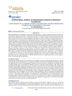
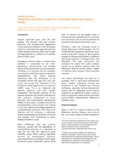
6 Advantages- Easy to install Easy to use Low cost Disadvantages- Difficult to troubleshot bus topology Heavy network traffic can slow down bus Failure of cable affects all devices 4. Mesh Topology: It is the topology in which every device has a dedicated point-to-point link to every other device. The term dedicated means that the link carries traffic only between the two devices it connects. Here Node 1 must be connected to n-1 nodes, Node 2 must be connected to n-1 nodes, finally node n must be connected to n-1 nodes. Therefore for mesh topology we need n(n-1)/2 duplex mode lines. Advantages- Privacy and security Easy fault identification & fault isolation Disadvantages- Difficult to install SIMULATION IN NS2 [Suryawanshi*et al., 5(12): December, 2016] ISSN: 2277-9655 IC Value: Impact Factor: http: // International Journal of Engineering Sciences & Research Technology [293] Topology IMPLEMENTATION Figure 1.
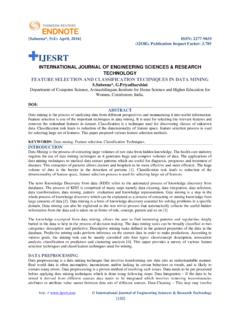
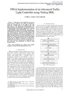
7 Star Topology The SIMULATION and IMPLEMENTATION of star topology using NS2 is shown in figure 1. Here switch is used as central device instead of hub. Five nodes are connected to switch with duplex links. Node 1 is the source node and node 3 is the destination. Node 1 will forward the data to switch first and then switch will send that data to specific destination node 3. Node 3 then will send acknowledgement to node 1. Here CBR traffic is assigned between node 1 & 3 shown by red color. 2. Ring Topology IMPLEMENTATION Figure 2. Ring Topology The SIMULATION and IMPLEMENTATION of ring topology using NS2 is shown in figure 2. Here seven nodes are used in ring topology. Node 0 is the source and Node 3 is the destination and data is send from node 0 to node 3 via node 1 [Suryawanshi*et al.]
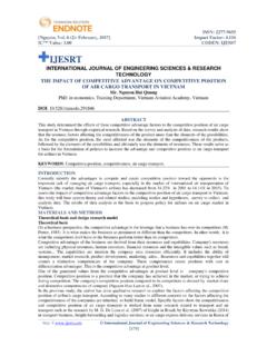
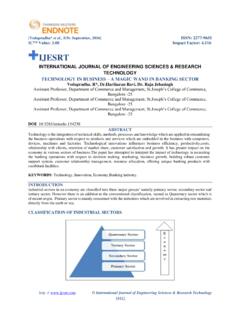
8 , 5(12): December, 2016] ISSN: 2277-9655 IC Value: Impact Factor: http: // International Journal of Engineering Sciences & Research Technology [294] & 2. 3. Bus Topology IMPLEMENTATION Figure 3. Bus Topology The SIMULATION and IMPLEMENTATION of bus topology using NS2 is shown in figure 3. Here five nodes are connected to central bus link. When any node wants to send data then that data will be send to all other nodes connected to bus via bus link and only destination node will accept data ,other all nodes will reject data. 4. Mesh Topology IMPLEMENTATION The SIMULATION and IMPLEMENTATION of mesh topology using NS2 is shown in figure 4 below. Here five nodes are connected using dedicated point-to-point link. Node 1 must be connected to n-1 nodes, Node 2 must be connected to n-1 nodes, finally node n must be connected to n-1 nodes.
9 Therefore for mesh topology we need n(n-1)/2 duplex mode lines. As five nodes are used therefore duplex mode links required will be this SIMULATION node 1 is source and node 4 is destination. Here FTP traffic is assigned between node 1 & node 4 shown by blue dedicated link are used this topology provides better security and privacy. [Suryawanshi*et al., 5(12): December, 2016] ISSN: 2277-9655 IC Value: Impact Factor: http: // International Journal of Engineering Sciences & Research Technology [295] Figure 4. Mesh Topology CONCLUSION In this paper, i have simulated the different types of network topology by configuring the number of nodes and network devices to it and shown how packets can be transmitted from node to node based on type of topology. Here i have used network simulator NS2 to simulate the different network topology and understand the practical concept of data communication over different network topology.
10 REFERENCES [1] Forouzan, Data Communication and Networking 5th Edition. [2] The Network Simulator ns-2:Documentation : [3] Marc Greis s tutorial.