Transcription of Design of Digitally Controlled Switch ed Mode …
1 IJISET - International Journal of Innovative Science, Engineering & Technology, Vol. 1 Issue 4, June 2014. ISSN 2348 7968 Design of Digitally Controlled Switched Mode Power Supply for Low Power High Frequency Application Soumya P Maharajanvar2, Shubha Rao K2, and S Chakravarthi3 1 Dept of Electrical and Electronics, BNM Institute of Technology, BSK 2nd stage Bangalore-70, Karnataka, India. 2 Dept of Electrical and Electronics, BNM Institute of Technology, BSK 2nd stage Bangalore-70, Karnataka, India. 3 Dept of Electronics and communication, BNM Institute of Technology, BSK 2nd stage Bangalore-70, Karnataka, India.
2 Abstract This paper describes the Design simulation and implementation of digital PID controller for the synchronous buck converter working in Continuous Conduction Mode (CCM) based on Field Programmable Gate Array (FPGA) device. The PID controller is implemented in Xilinx ISE digital Design environment with Matlab/Simulink simulation and testing environment, through Xilinx System Generator toolbox. The converter operates at a switching frequency of 500 KHz. First the PID controller is designed using Simulink toolbox from Matlab to generate the required set of coefficients to meet the start-up and the transient characteristics.
3 The controller is then realized using Xilinx System Generator (XSG) block set. Keywords: Continuous Conduction Mode; FPGA; XSG. 1. Introduction DC-DC switching power supplies are used extensively in all areas of work and daily life. Compared with linear power supplies, Switching Mode Power Supplies (SMPS) provide high efficiency, easy integration, small dimensions and weight. Due to these advantages, SMPS have been widely used in numerous portable personal communication systems such as cell telephones, MP3 player and other PDA products, which have grown explosively in recent years.
4 Being widely used in the new generation portable systems, the regulation requirement for low-power high-frequency integrated DC-DC switching mode power supply converter systems becomes more and more demanding in the industry. Normally analog control provides a very fine resolution in the output voltage. The output voltage can be adjusted to any arbitrary value, which is only limited by loop gain and noise levels. Digital control is not new in the field of Power Electronics. Based on Digital Signal Processor (DSP) or other processor, it has been applied for several years in motion control, and in medium to high power line-frequency based application such as rectifier, inverters and uninterruptable power supply (UPS).
5 The advantages of digital controller are, Advanced control algorithms implementation Flexibility and programmability Size miniaturization and high frequency Less susceptible to component and variations Alleviation for the limitation of bandwidth and large gain variation in control law. In order to avoid the tedious way of implementing the controller, a newly created simulation toolbox called Xilinx System Generator (XSG) - a toolbox working in the MATLAB/Simulink environment can be used not only to simulate exactly the hardware but also to automatically generate the VHDL code needed for the implementation.
6 The user is provided with a library of blocks representing functions which can be implemented in an FPGA. The use of the XSG has two main advantages over traditional methods. First, the implemented algorithm is guaranteed to function exactly as in the simulation and second, there is no need to create two different models (one for the simulation and one for the implementation). The paper is organized as follows: Section 2 is small signal mathematical model of buck converter. Section 3 describes detailed Design of PID controller and stability of converter.
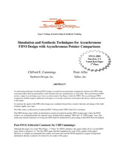
7 Design flow using XSG is given in Section 4. The simulation results obtained by this control technique are given and compared in Section 5. Conclusions are drawn is section 6 2. Mathematical Model of Buck Converter The schematic diagram of the proposed dc-dc buck converter system is shown in Fig. 1. The mathematical 529 IJISET - International Journal of Innovative Science, Engineering & Technology, Vol. 1 Issue 4, June 2014. ISSN 2348 7968 model takes the series resistances of the inductor and the capacitor in to account.
8 The capacitor ESR, RC, introduces a zero frequency to the transfer function. Fig. 1 Buck converter circuit model Based on the useful state-space averaging model, the transfer functions of a switched buck converter can be developed using small signal analysis. Considering the Current Continuous Condition (CCM) mode, the transfer function of the buck converter can be written in continuous-time s-domain The transfer function for the above buck converter model is found using state space averaging model and is given by: ( ) ( )=( +1) 2 1+ + + + + + +1 (1) 3.
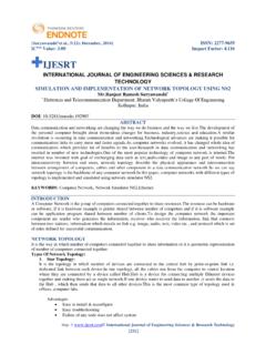
9 Controller Design Figure 2 shows the overall system model, which contains, the PID controller, the Converter, the ADC and DPWM built from standard Simulink blocks. Fig. 2 Block diagram of the complete closed loop system The PID controller is the most c ommon type of digital control used in Digitally - Controlled high-frequency and low-power integrated SMPS. Here a discrete-time PID controller is designed to be implemented in FPGA. Modeling of PID Controller Let e(t) be the input and d(t) be the output of the controller. A continuous-time PID controller is given by: ( )= ( )+ ( ) 0+ ( ) (2) The discrete-time filtered PID controller can be written as ( )= 0 2+ 1 + 2( 1)( + 1) (3) Where 0, 1, 2and 1 are the controller parameters to be determined by the pole placement method.
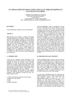
10 The digital control system including the PID controller and a buck converter is shown in figure 3 Fig. 3 Block diagram of PID- Controlled buck converter The closed loop transfer function is: = ( ) ( )= ( ). ( )1+ ( ). ( ) (4) Setting 1 0 = 1 and 2 0 = 2 to cancel the poles of P(z) with the zeros of ( ) Then we get T= 0 1 + 0 2 2+ 1 + 2 (5) Where 1and 2are to be determined by the desired closed-loop dynamics which correspond to the second-order dynamics with a pulsation and a damping ratio (in s-domain 2+2 + 2 ).