Transcription of Simultaneous Removal of Particles from Front and Back ...
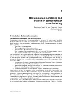
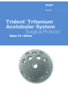
1 Simultaneous Removal of Particles from Front and Back Sides by A Single Wafer Backside Megasonic System Chan Geun PARK1, a and Hong Seong SOHN1,b 1. Akrion Systems LLC, 6330 Hedgewood Drive, Suite #150, Allentown, PA 18106, USA. a Keywords: backside megasonic, backside clean, particle Removal efficiency. Introduction In IC manufacturing, particle Removal from a wafer's back side (BS) has become as important as that from the Front side (FS). For example, during lithography, BS Particles can cause a variation on the topside surface topography. This may result in a focus-spot failure due to the reduced process window for depth of focus (DOF) as shown in Fig. 1. This problem increases as the feature size decreases. BS Particles may cause other problems in wet benches, where BS Particles can be transferred to the adjacent Front side of wafers. Fig. 2 shows these FS Particles , which usually appear as flow or streak patterns on the wafer [1]. Fig. 1 Impact of BS Particles on FS patterning: Fig.
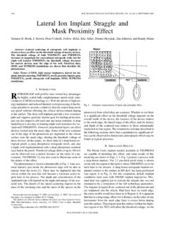
2 2 Typical flow type defects caused by the particle (a) map of pattern defectivity and (b) SEM image transfer from BS to FS in a wet bench; (a) streaks on (a) bare of these pattern defects silicon wafer, (b) patterned wafer and (c) its SEM image The typical source of BS Particles is wafer handling with either an electrostatic or vacuum chuck or from plates and stages in the vacuum chamber which result in defect maps as shown in Fig. 3. For pre-lithography BS particle cleans, these Particles are generated mainly during dielectric deposition, metal sputtering or implant/ash. Because of the typical elevated temperature in the vacuum process, Particles can adhere strongly to the Fig. 3 Typical BS Particles generated during a vacuum process; (a) BS particle map after CVD and (b) SEM. wafer backside. Compounding the issue, the image and its EDX analysis spectrum of BS particulates introduction of immersion lithography for advanced device fabrication brings increased concern about the presence of loose films and Particles that can accumulate at the wafer edge (bevel and apex).
3 The wafer undergoes multiple wafer processing steps in the device flow and contamination can be introduced at each step. Because of the high throughput requirements for scanners, the immersion hood water layer moves at speeds of about and this Fig. 4 Wafer edge defect migration concern at exerts high capillary forces from the trailing edge of immersion lithography process the water meniscus that can dislodge defects from the edge and re-deposit them on the Front side of the wafer as shown in Fig. 4. Table 1. Particle size requirements from ITRS 2008. [2] While the critical particle size for BS is larger than FS, it tends to decrease as the feature size decreases as indicated by Table I. [3]. So far most silicon wafer cleaning tools have been developed in order to remove FS Particles by physical force and/or chemical reaction. Whenever BS cleans are needed, wafers are flipped over before and after cleaning or cleaned by indirect physical force transmitted through the wafer with chemicals dispensed to the back side of the wafer.
4 But, in these cases, BS particle Removal efficiency (PRE) is much lower than FS PRE. In this paper a new single wafer megasonic system was introduced and both FS and BS PREs were evaluated as a function of megasonic power/time and source of contamination. Experimental Experiments were performed on a 300mm Akrion Systems Goldfinger Velocity tool. Megasonic sound energy is delivered to the wafer back side directly through a plastic-covered piezoelectric material to a liquid meniscus pathway provided by the BS megasonic system (BS Meg) installed beneath the wafer. The picture of the BS Meg-meniscus between BS. Meg and wafer back side and the sound transmission schematic are shown in Fig. 5. For the particle Removal experiments, 300mm bare silicon wafers were contaminated with Si3N4. Particles (200nm in diameter and around 20,000. Particles per wafer) or in a metal sputtering chamber after the wafer was flipped. The number of Particles on the wafer was counted from Fig. 5 GoldFinger BS Megasonic system and its schematic diagram of the sound transmission path 65nm-size by SP2 (KLA-Tencor) before and after contamination and after cleans.
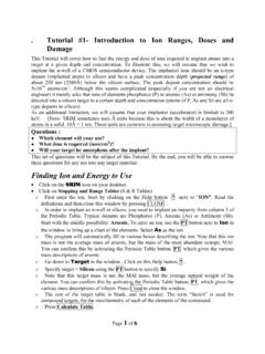
5 Results and Discussions Front and back side particle Removal efficiencies for Si3N4 Particles were evaluated as a function of BS Meg power and time by dispensing dilute SC1 to wafers. Fig. 6 shows that back side PRE with the BS Meg and SC1. already reached >85% at 70W and 30 second condition, Back side PRE by BS Meg was almost 7 times higher than BS PRE of the Goldfinger . Front side megasonic system (FS Meg). Front side PRE was comparable using either Fig. 6 Backside (BS) PRE in SC1 as functions of BS Meg megasonic as shown in Fig. 7. This indicates that power and time the BS Meg is able to remove Particles from both the Front and back sides at the same time with sufficiently high PRE. Figure 8 shows results of PRE testing for the difficult Removal of Electrostatic Chuck (ESC). Fig. 7 Front side (FS) PRE in SC1 as functions of BS Fig. 8 Backside PRE comparisons on ESC marks when BS. Meg power and time and FS Meg and a scrubber were employed Marks. Testing was done to compare performance of the BS Meg to the FS Meg and a typical back side scrubber.
6 Contaminated wafers were cleaned with SC1 for 30 seconds. BS megasonic power ranged from 30 to 100 Watts and FS megasonic power was directly applied to the Front side of the wafer. The BS megasonic performed best with a PRE of ~ 35%. The FS meg PRE was ~ 25%, while the scrubber produced ~15% PRE. It is interesting to note that the BS megasonic outperformed the scrubber even at low power settings. Advanced Applications The system can be set up to clean without damage in applications where the Front side has damage sensitive critical structures such as for 32nm gate-poly (AR>5:1) patterned wafers. This is accomplished by modifying the back side chemical nozzles and recipe configuration, and leaving the Front side dry as shown in Fig. 9. While bubble explosions enhanced by only 10 Watts of megasonic energy could cause physical damage if the Front side is wet, this does not happen even with 100 Watts of megasonic energy transferred through silicon wafer and air. Chemical/DIW supplied to the back side does not flow over the wafer edge to the Front side during the whole process.
7 The result is that only about 10 Particles (> 65 nm) per wafer were added after the SC1 BS Meg clean. Fig. 9 Feature and evaluation results of Front side dry BS meg process As Fig. 4 illustrates, wafer edge and bevel clean are serious issues in need of a solution, so Akrion Systems developed a process that couples the Goldfinger Front side megasonic system (FS Meg) to its BS Meg process. Fig. 10 shows how this merged process works. The Goldfinger Meg is pulled out to the edge area and applied simultaneously with the BS Meg to reinforce cleaning efficiency at the edge and bevel area. Particle maps and SEM inspection before and after the clean confirmed that PRE at the edge and bevel was much improved. Fig. 10 Feature and evaluation results of Edge/Bevel-Focused Goldfinger Megasonic Clean Electrostatic chuck (ESC) mark is a common backside contamination and remains after a variety of micro-fabrication processes such as lithography, ion implantation , plasma etch, film deposition, and inspection.
8 ESC grips a wafer so strongly with the attraction of opposite charges of insulating and conducting substrates that it is not easy to remove chuck marks. This is especially true in the case of CVD, because the process temperature is relatively high (~400 C). It is more difficult to detach the marks so firmly adhered to the wafer. Hence, we pre-treated the wafer with dilute HF (DHF) just prior to BS Meg process in order to lift off the carbon-based contamination and boost efficiency of the BS Meg. Fig. 11 back side particle maps show that severe circular ESC marks (contaminated in a CVD chamber) were almost completely removed by the Fig. 11 Backside particle maps of the wafer contamintaed in CVD. process of DHF-BS Meg clean. chamber before/after DHF-preteated BS Meg clean Conclusions In this study, an Akrion Systems' designed single wafer back side megasonic system was demonstrated to be capable of removing contaminants from both sides of a wafer concurrently. Depending on incoming wafer condition, the system is also able to clean the wafer back side only, thus protecting critical patterns from any physical/chemical damages.
9 Furthermore, the system can be modified to reinforce cleaning efficiency at the wafer edge/bevel area. This was confirmed with PRE. evaluation and SEM inspection. The experiment also revealed that DHF pre-treatment is helpful to remove strongly adhered ESC marks. References [1] HS Sohn, et al.: Removal of Backside Particles by a Single Wafer Megasonic System, 212th ECS. Meeting, 2007. [2] Motoya Okazaki, et al.: Wafer Edge Polishing Process for Defect Reduction during Immersion Lithography, Proc. SPIE, Vol. 6922 (2008). [3] ITRS Roadmap 2008: Front End Surface Preparation Technology Requirements