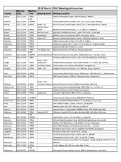
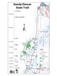
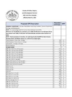
Transcription of Site Evaluation For Stormwater Infiltration 1002
1 WDNR September 2017 WISCONSIN DEPARTMENT OF NATURAL RESOURCES TECHNICAL STANDARD SITE Evaluation FOR storm water Infiltration 1002 DEFINITION This standard defines site Evaluation procedures to: (1) Perform an initial screening of a development site1 to determine its suitability for Infiltration , (2) Evaluate each area within a development site that is selected for Infiltration , and (3) Prepare a site Evaluation report. PURPOSE (1) Protect groundwater from surface water pollution sources, (2) Identify areas suitable for Infiltration , (3) Establis h methods to a) characterize the site, and b) screen for exclusions and exemptions under ch. NR 151, Wis. Adm. Code, (4) Establis h requirements for siting an Infiltration device and the selection of design Infiltration rates, (5) Define requirements for a site Evaluation report documenting that appropriate areas are selected for Infiltration and that an appropriate design infiltr ation rate is used, and CONDITIONS WHERE PRACTICE APPLIES This standard is intended for development sites being considered for storm water Infiltration devices.
2 Additional site location requirements may be imposed by other storm water infiltr ation device technical standards . Be aware of applicable federal, state and local laws, rules, regulations or permit requirements governing Infiltration devices. This standard does not contain the text of federal, state or local laws. Note that Infiltration devices are commonly regulated as plumbing when in connection with a piping system, see ch. SPS 382, Wis. Adm. Code. This technical standard enables state and local authori ties to implement Infiltration requirements with uniformity. CRITERIA The site Evaluation consists of four steps (Steps A D) for locating the optimal areas for Infiltration and establishing the design infilt ration rate for properly sizing Infiltration devices (below, and Fi gure 1). To avoid costly redesigns, it is recommended to complete Step A before the preliminary plat, and Step B before the final plat or Certified Survey Map (CSM) is approved. For regional Infiltration devices, and for devices constructed on public right-of-ways, public land, or jointly owned land, Step C should be completed before the final plat or final CSM approval.
3 Infiltration devices distributed around a development will usually better sustain the existing hydrology, and can improve the lif espan of devices, compared to a single regional device. Information collected in Step A may be used to explore the potential for multiple infiltr ation areas versus a regional device. 1 Words in the standard that are shown in italics are described in the Defini tions section. The words are italicized the first time they are used in the text. Technical standards are reviewed periodically and updated if needed. To obtain the current version of this standard, contact your local WDNR office or the standards Oversight Council offi ce in Madison, WI at (608) 441-2677. WDNR September 2017 1002-TS-2 Step A. Initial Site Screening Step B. Preliminary Field Veri fication of the Initial Site Screening Step C. Establis hment of Design Infiltration Rate Step Field Evaluation of Specific Infilt ration Areas Step Infilt ration Rate Exemption Step Infilt ration Rate Determination Infiltration Option 1 Infiltr ation Rate Not Measured, Soil Compaction Mitigated Infiltration Option 2 Infiltr ation Rate Measured with In-Field Device, Soil Compaction Mitigated Infiltration Option 3 Infiltr ation Rate Not Measured, Soil Compaction Not Mitigated Step D.
4 Soil and Site Evaluation Report Figures and Attachments: Figure 1. Site Evaluati on for Infiltration Flow Chart Figure 2. Example Bioretention Basin Section Figure 3. Example Bioretention Basin Section with Underdrain Section Figure 4. Example Infiltration Basin Section Atta chment 1. Hydrologic Condition Form Atta chment 2. Soil and Site Evaluation Form Record information for Steps B and C as noted in Step D. Prepare a single report for the infilt ration Evaluation . Step A. Initial Site Screening The purpose of Step A is to use existing available information to determine if installation is limited by s. NR (3)(a) or (4), Wis. Adm. Code, and where field work is needed for Step B. A wetland determination or delineation may be needed to identify boundaries of wetlands within or near the site, but is not required as part of the soil Evaluation . The initial screening may be conducted without fieldwork to determine the following: (See a list of references and resources in the Considerations section).
5 (1) Site topography and slopes greater than 20%, (2) Site soil Infiltration capacity characteristics as defined in NRCS County soil surveys or other relevant source, (3) Soil parent material obtained from published soil descriptions, (4) Hydrologic condition based on the condition values for the current and two previous months rainfall (Attachment 1), (5) Soil map unit, depth to groundwater and depth to restrictive features; use seasonally high groundwater information where available, (6) Distance to sites listed on the Wisconsin Remediation and Redevelopment Database (W RRD) sites within 500 feet from the perimeter of the development site, WDNR September 2017 1002-TS-3 (7) Known presence of endangered species habitat, (8) Location of rivers, streams, lakes, and floodplains, (9) Location of mapped wetlands, hydric soil and potentially hydric soil based on the Wisconsin wetland Inventory (WWI), which can be accessed via the WDNR Surface W ater Data Viewer, (10) Areas prohibited from installation of storm water Infiltration devices by s.
6 NR (3)(a) and (4)(a), Wis. Adm. Code, including, but not limited to, setbacks from direct conduits to groundwater such as wells , sinkholes, and karst features due to the potential for groundwater contamination, (11) Areas exempt from the requirement to install storm water Infiltration devices by ss. NR (3)(b) and (4)(c) Wis. Adm. Code, (12) Potential impact to utilities, and (13) Potential impact to adjacent property. Step B. Preliminary Field Verification of the Initial Site Screening The purpose of Step B is to field-verify information from Step A for all potential areas of the development site considered suitable for Infiltration . Evaluate the areas for depth to groundwater, depth to bedrock, and soil texture to verify any exemption and exclusion found in Step A. Soil borings are acceptable for Step B. Sandy loams, loams, silt loams, silts and all clay textural classifications are assumed to meet the percent fines limitations of a filt ering layer in s. NR (14r), Wis.
7 Adm. Code, for both 3 and 5 foot soil layers. Coarse sand does not meet s. NR (14r), Wis. Adm. Code, limitations for a 3 foot soil layer consisting of 20% fines. Other sand textures and loamy sands may require the percent fines level be veri fied with a sieve analysis. Step C. Establishment of Design Infiltration Rate The purpose of Step C is to determine if locations identified for Infiltration devices are suitable for Infiltration and to provide the required information to design the device. Test pits are required for Step C. If a backhoe is unable to excavate a test pit to the required depth, then soil borings may be used to evaluate the depth below that which the backhoe is able to reach. It is expected that a medium-sized backhoe can reach at least 15 feet below grade. Information from soil borings and monitoring well logs may supplement data from test pits. Refer to Attachment 2 for a soil and site Evaluation form. Step Field Evaluation of Specific Infiltration Areas.
8 Construct the minimum number of test pits for each Infiltration device as defined in Table 1. Local agencies may require additional test pits for soil Evaluation . Excavate test pits to a depth of at least 5 feet below the native soil interface elevation (Figures 2 4) or to a limiting layer, such as bedrock or groundwater. If no limiting layer is encountered, continue excavation to 5 feet below the native soil interface even if perched condit ions are encountered. For example, if the native soil interface of an Infiltration device is 8 feet below the existing grade, a test pit at least 13 feet deep will be needed (8 feet plus 5 feet). Follow OSHA safety protocol for designing and entering test pits. To avoid entering test pits, soil may also be examined from the surface as it is excavated. Complete morphological soil profile description using the NRCS Field Book for Describing and Sampling Soils, (latest edition). Soil profile descriptions are to be made by a professional meeting the Qualifications (see Step D).
9 Document the test pits using the Soil Test Pit Evaluation form in Attachment 1. WDNR September 2017 1002-TS-4 Table 1. Evaluation Requirements to Proposed Infiltration Devices Note 1 Infiltration Device (Technical Standard Note 2, Note 3) Tests Required Minimum Number of Test Pits Required Note 4, Note 5 Rain Garden Soil texture Evaluation or Infiltration test N/A Infiltration Trenches (1007) Test pits 1 test pit/100 linear feet of trench with a minimum of 2 test pits, and sufficient to determine / confirm vari abilit y Vegetated Swale (1005) Test pits 1 test pit/ 500 linear feet of swale with a minimum of 2 test pits, and sufficient to determine / confirm vari ability Bioretention Systems (1004) Test pits 1 test pit or a number sufficient to assess Infiltration potential, and sufficient to determine / confirm variability Surface Infiltration Basins (1003) Test pits 2 test pits then an additional test pit /10,000 square feet and sufficient to determine / confirm variability Subsurface Dispersal Systems (N/A)
10 Greater than 15 feet in width Test pits 2 test pits then an additional test pit /10,000 square feet and sufficient to determine / confirm variability Permeable Pavement Systems (1008) Test pits 2 test pits then an additional test pit /10,000 square feet and sufficient to determine / confirm variability Note 1 Maintain trench safety requirements; test pit evaluations can be made from the surface without entering the pit. Note 2 Technical standards refer to the corresponding WDNR design technical standard containi ng design criteria for this practice. Note 3 Where initial site borings show uniform soils throughout the site, the professional meeting the Qualifications (s ee Step D) may reduce the number of test pits, provided information from both test pits and soil borings confirm a uniform soil condition across the proposed device location. Note 4 Test pits are optimally located within 10 feet of the footprint perimeter, and not with in the footprint. Note 5 If a backhoe is unable to excavate a test pit deep enough from the existing surface to reach 5 feet below the native soil interface, then soil borings may be used to evaluate the depth below the which the backhoe is unable to reach.