Transcription of SLAC-PUB-8907 September 2002 A SOLID STATE …
1 A SOLID STATE MODULATOR FOR DRIVING SLAC 5045 KLYSTRONS* de Lamare, Cassel, Nguyen, Pappas, Donaldson Stanford Linear Accelerator Center, Stanford, CA 94309 * Work supported by the Department of Energy contract DE-AC03-76SF00515 Abstract A test is ongoing at the Stanford Linear Accelerator Center (SLAC) where a SOLID STATE induction modulator is driving a SLAC 5045 klystron. The modulator generates 22 kV, 6 kA pulses that are stepped up by a 15:1 transformer that is a part of the klystron s pulse tank. The modulator s pulse duration is adjustable up to the volt-second limit of its cores, and it is capable of a pulse repetition frequency up to 120 Hz.
2 The modulator s design, construction, and experimental results are the focus of this paper. I. INTRODUCTION The two mile long linear accelerator at SLAC uses RF driven accelerator sections to accelerate electron and positron beams up to a maximum of 55 GeV. Each accelerator section is driven by a SLAC 5045 klystron; see Table 1 for klystron parameters. There are 244 klystrons in the Linac, and a thyratron modulator powers each one. The modulator has a pulse forming network (PFN) with tunable inductors, and it is charged to and discharged through a thyratron into a 15:1 pulse transformer in a pulse tank at the base of the klystron. The modulator generates a pulse of , 6kA at 120Hz. The modulator reliability is strongly tied to the operation of the thyratron [1].
3 Many man-hours are spent ranging thyratron reservoirs and tuning PFNs. If the thyratron switch is replaced with an IGBT, then a PFN is no longer needed to form a square pulse. A modulator with neither a thyratron nor a PFN can significantly reduce the needed manpower to maintain the Linac modulators. Klystron Frequency 2856 MHz Klystron Beam Voltage 350 kV Klystron Beam Current 414 A Microperveance 2 Peak Power Out 67 MW RF Pulse Width s Table 1. SLAC 5045 Klystron Specifications The PFN modulators at SLAC were designed in the 1960s and improved in the 1980s. At the time, thyratrons were the only viable switch for this high peak power system (150MW). In recent years, high power SOLID STATE switches have become more available particularly IGBTs.
4 As more power modulators are converted to SOLID STATE switch designs, the thyratron market will fade, and SLAC could have some difficulty in maintaining the Linac as it exists today. A SOLID STATE klystron modulator design may keep SLAC performing valuable physics research in the years ahead. II. MODULATOR DESIGN For the past several years, SLAC, LLNL, and Bechtel Nevada have been pursuing a SOLID STATE modulator design for the Next Linear Collider (NLC) [2]. In support of that effort, a smaller modulator was constructed using pieces from the NLC modulator design to drive a SLAC 5045 klystron [3]. This modulator, often referred to as the 10-Stack modulator, consists of ten sections (cells) of double driven metglass cores stacked to form a 10:1 transformer with ten independent and grounded primary turns and a single secondary turn.
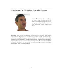
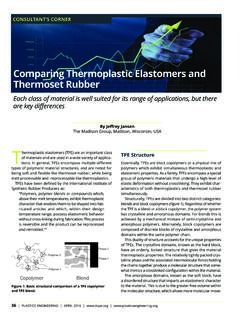
5 Two core driver boards one master and one slave, drive each primary turn. A core driver board consists of an IGBT, an IGBT gate driver, energy storage capacitor, energy recovery diode and capacitor, and a core reset driver (on the master board only). See Figure 1 for the cell schematic and Figure 6 for the ten stack modulator schematic. The cells have a low inductance, and the IGBT gate drivers are designed such that the collector to emitter current of the IGBT has a high di/dt. Figure 1. Core Driver Circuit DRIVER CONSTRUCTION A. IGBT The IGBT is a Eupec FZ800R33KF1. It is a , 600A device, and it was chosen for its high voltage rating, fast switching times, and for the absence of a turn-off tail.
6 Higher voltage IGBTs are available, and they are being considered for future designs. The higher the voltage of the IGBT, then the fewer the cells needed to get the SLAC-PUB-8907 September 2002 Presented at the 28th International Conference on Plasma Science (ICOPS 2001) and 13th International Pulsed Power Conference (IPPC 2001) , 6/17/2001 - 6/22/2001, Las Vegas, Nevadarequired output voltage; this may reduce the overall modulator cost. B. Energy Storage Capacitor The energy storage capacitor is a segmented , metalized polypropylene capacitor manufactured by NWL. It is , 5kV, and low inductance. There are two capacitors per core driver board. A capacitor with a high energy density is desirable so to minimize the pulse droop.
7 The peak current in each capacitor is 1500A for 3 s at 120Hz. If the pulse droop is significant, then extra cells are needed in the modulator for droop compensation. C. Core There are three different types of cores used in the 10-stack modulator. The most numerous is the National Arnold 2605SA1 Metglass core with Namalite insulation. There are also some Hitachi FT-2M Finemet cores and some National Arnold CRMW2 nano- crystalline cores. All of the cores have the same dimensions: ID, OD, and Ht. The core fits into an assembly that forms the primary winding of the transformer. The assembly includes a coil of tubing which provides the necessary cooling for the core and the IGBTs. On the outside diameter of the assembly are two flats where the IGBT heat sinks make contact.
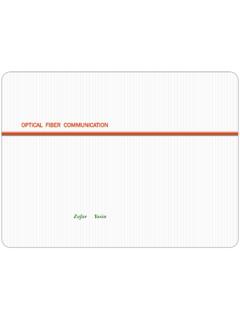
8 The core is potted into the assembly to provide the necessary insulation for operation. When two core assemblies are stacked, there is a notch wide enough for the core driver boards to slide into place and make electrical contact with the primary winding. Figure 2. Driver board with partial view of core case. D. Diode The diode is a Westcode SM35 HXC103. It is a diode with a Qrr of 33 C. The diode is mounted in an aluminum can to minimize its inductance. The can has a spring washer inside to maintain the necessary pressure on the diode. When the IGBT turns off, the diode must turn on quickly to direct the energy stored in the circuit s inductance and the core s magnetizing current into the energy recovery capacitor.
9 The diode inductance and forward recovery should be minimized, since any added voltage during the diode s turn on will add to the voltage on the energy storage capacitor and possibly damage the IGBT. The diode must also have a low Qrr if the cell will be used for droop compensation. E. Energy Recovery Capacitor The energy recovery capacitor is a 130uF, 250V capacitor used to store the energy from the core when the IGBT turns off. This capacitor, like the diode, must be low inductance to protect the IGBT. The capacitor is charged to 200 VDC to aid the energy capture. The 200 VDC input is also used to charge the core reset driver capacitor bank. F. Core Reset Driver The core is reset with a 200V, 100A pulse prior to the main trigger pulse.
10 The driver consists of a capacitor bank, series IGBTs, and control circuitry. The main trigger for a cell will only commence if the reset current exceeds a measured threshold. G. IGBT Driver At the core of the IGBT driver is a Concept Driver. A booster circuit made of a capacitor and a fast SCR assists the Concept Driver to improve the turn on characteristics of the IGBT. For a thorough description of the IGBT driver circuit, refer to Reference [4]. H. Trigger Distribution The trigger distribution board fans out one of two trigger inputs into any of the ten cell s master core driver boards. The core reset is triggered first. If the core reset on a cell is sufficient, then the trigger distribution board triggers the master and slave core driver boards.