Transcription of Slider – Crank Mechanism for Demonstration and …
1 Slider Crank Mechanism for Demonstration and Experimentation MQP. Advisor: Eben C. Cobb ERIC BRIGHAM. CHRIS DESTEFANO. ZACHARY KILLOY. Date Submitted: April 25, 2013. Slider Crank Mechanism for Demonstration and Experimentation Abstract The Slider - Crank Mechanism is a particular four-bar linkage configuration that exhibits both linear and rotational motion simultaneously. This Mechanism is frequently utilized in undergraduate engineering courses to investigate machine kinematics and resulting dynamic forces. The position, velocity, acceleration and shaking forces generated by a Slider - Crank Mechanism during operation can be determined analytically. Certain factors are often neglected from analytical calculations, causing results to differ from experimental data. The study of these slight variances produces useful insight. The following report details the successful design, fabrication and testing of a pneumatically powered Slider - Crank Mechanism for the purpose of classroom Demonstration and experimentation.
2 Transducers mounted to the Mechanism record kinematic and dynamic force data during operation, which can then be compared to analytical values. The Mechanism is capable of operating in balanced and unbalanced configurations so that the magnitude of shaking forces can be compared. The engine was successfully manufactured and operates as intended. Data recorded by the device's accelerometers is comparable to calculated values of acceleration and shaking force. Page i Slider Crank Mechanism for Demonstration and Experimentation Contents Abstract ..i Executive Summary .. 3. Design Description .. 4. 4. TASK 4. DECISION MATRIX .. 5. BACKGROUND ..6. SOLID 7. DESIGN FOR 9. TRANSDUCER SELECTION .. 11. Analysis .. 13. KINEMATIC 13. Position Analysis .. 13. Velocity Analysis .. 15. Acceleration Analysis .. 17. Dynamic Force Analysis ..19. TORSIONAL STRESS ANALYSIS OF CRANKSHAFT.
3 28. FINITE ELEMENT ANALYSIS OF CRANKSHAFT .. 32. TORSIONAL VIBRATION ANALYSIS OF CRANKSHAFT .. 41. CROSSHEAD GUIDE DEFLECTION 42. CROSSHEAD GUIDE NATURAL FREQUENCY ANALYSIS .. 44. DAMPER SELECTION THROUGH VIBRATION 45. PIN STRESS ANALYSIS .. 47. PRELIMINARY VALVE Cylinder Pressurization Experimental Evaluation of Mass Flow through System ..48. LIMITATIONS AND VARIATIONS ..50. Page 1. Slider Crank Mechanism for Demonstration and Experimentation CRANKSHAFT OPERATIONS AND FOURTH AXIS MACHINING .. 51. MACHINING IMAGES .. 56. Results of Initial 62. Slider ACCELERATION AND CYLINDER PRESSURE .. 62. SHAKING 65. Comparison of Analytical and Experimental 68. 70. 71. Recommendations for Future MQPs .. 72. Figures .. 74. Bibliography .. 77. Appendices .. 78. Page 2. Slider Crank Mechanism for Demonstration and Experimentation Executive Summary The Slider - Crank Mechanism is a particular four-bar linkage configuration that converts linear motion to rotational, or vice versa.
4 Internal combustion engines are a common example of this Mechanism , where combustion in a cylinder creates pressure which drives a piston. The piston's linear motion is converted into rotational motion at the Crank through a mutual link, referred to as the connecting rod. As the geometry of the Crank forces the conversion of linear motion to rotational, shaking forces are generated and applied to the Crank 's housing. These shaking forces result in vibrations which impede the operation of the engine. The Slider - Crank Mechanism is frequently utilized in undergraduate engineering courses to investigate machine kinematics and resulting dynamic forces. The position, velocity, acceleration and shaking forces generated by a Slider - Crank Mechanism during operation can be determined analytically. Certain factors are often neglected from analytical calculations, causing results to differ from experimental data.
5 The assumption is frequently made that the crankshaft's angular velocity is constant. In reality, angular velocity is slightly higher on the power stroke than the return stroke. The study of these slight variances produces useful insight into the characteristics of piston driven engines. The following report details the successful design, fabrication and testing of a pneumatically powered Slider - Crank Mechanism for the purpose of classroom Demonstration and experimentation. Complete analysis of the engine's kinematics was performed, assuming a constant angular Shaking forces of the unbalanced Mechanism were calculated and balancing weights were designed for statically and dynamically balanced configurations at the same constant angular velocity. Transducers mounted to the Mechanism were used to record kinematic and dynamic force data during operation, which was then compared to the analytical values.
6 The engine was successfully manufactured and operates as intended. Data recorded by the device's accelerometers is comparable to calculated values of acceleration and shaking Satisfactory operation of the engine was achieved with minimal tuning. The engine is capable of operating at angular velocities ranging from 80 to 330 RPM, using a balancing weight optimized for 200 RPM. Sustained motion is achievable with cylinder pressures as low as , with a loss of only 2 psi through the system. The reduction in shaking force achieved through use of the balance weights is apparent both visually and in recorded data. All experimental values were reasonable when compared with analytical calculations. Page 3. Slider Crank Mechanism for Demonstration and Experimentation Design Description Objective The objective of this MQP is to fabricate a working model of a Slider Crank Mechanism that demonstrates the associated motion and provides means to measure kinematic properties, dynamic forces and cylinder pressure in various states of balance.
7 Task Specifications 1. The Slider - Crank Mechanism 's motion must be visible. 2. The Mechanism must be able to sustain motion when acted on by a driving force. 3. Removable balance weights must be incorporated into the design. 4. The Mechanism must be capable of operating in both balanced and unbalanced states. 5. A means of measuring and recording the kinematic and dynamic characteristics of the Slider - Crank Mechanism 's motion must be incorporated into the design. 6. All components of the Mechanism must be exhibit a safety factor of 5 in regards to static failure. 7. The Mechanism , all equipment required for operation and data acquisition must be portable and self-contained. 8. The total width of the unit must not exceed feet, to allow for transport through a doorway. 9. The Mechanism must be operable by one individual. 10. All moving components must operate behind a safety shield.
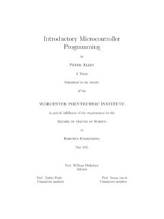
8 11. The Mechanism must be manufactured within the MQP's cost constraints. 12. Design, manufacturing and experimentation must be completed within the allotted time. Page 4. Slider Crank Mechanism for Demonstration and Experimentation Decision Matrix Figure 1: Decision Matrix used to rank proposed designs Page 5. Slider Crank Mechanism for Demonstration and Experimentation Background The assembly of a piston, cylinder, connecting-rod and crankshaft is the classic form of the Slider - Crank Mechanism . In general a Slider Crank transmits motion generated by the linear displacement of the piston by a working fluid to rotational motion of a shaft. There are many applications of Slider cranks and among the most common are engines. The use of these mechanisms for power generation began with the steam engine in the late 18th century and has developed into possibly its most recognizable form as the current day internal combustion engine.
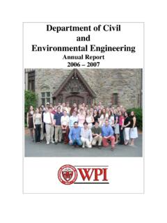
9 A single piston engine model could serve as a functional, eye-catching example of a Slider - Crank . Elmer's Standby Single-Acting, Single Piston Pneumatic Engine: The Standby single acting, single piston pneumatic engine is one example of a Slider Crank Mechanism . This engine utilizes a piston-wrist-pin-connecting rod construction that resembles an automotive engine. This type of engine provides a clear visual of the kinematics of a Slider Crank . The design can be powered by compressed air or steam and is driven by pressure applied to one side of the piston within the cylinder. The single acting nature of this engine also more closely resembles the operation of an internal combustion engine. The design is simpler than alternative pneumatic and steam engines based on its lack of external eccentric valve gear. The design uses grooves on the crankshaft to port air into and out of the cylinder at specific times in its rotation.
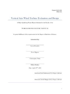
10 By attaching pressure transducers and accelerometers to this design it would be possible to relate cylinder pressures to the Mechanism 's kinematics. The crankshaft in this design would also be easily modified in order to create detachable balancing weights to demonstrate shaking forces for unbalanced, overbalanced and perfectly balanced situations. Figure 2: Elmer's Standby Model Engine Page 6. Slider Crank Mechanism for Demonstration and Experimentation Solid Modeling The Standby engine utilizes a valve system which is integrated into the crankshaft. This design characteristic was incorporated into the Demonstration device. Figure 3: Isometric View Solid Model of Slider Crank Mechanism Figure 4: Top View Solid Model of Slider Crank Mechanism Page 7. Slider Crank Mechanism for Demonstration and Experimentation Figure 5: Assembly Drawing for Slider Crank Mechanism Figure 6: (Left) Solid Model of Crankshaft Top View; (Right) Solid Model of Crankshaft Isometric View Page 8.