Transcription of Small CellS and diStributed antenna SyStemS
1 Small CellS and diStributed antenna SyStemS Strategic White PaPer diStributed antenna SyStemS (DaS) often provide wireless coverage in areas experiencing poor signal strength; for example, tunnels, large venues, and shopping malls. Similarly, Small CellS have also initially targeted weak coverage areas. While they both seem to target the same applications, there can be significant architecture and design differences between them depending upon the situation being of ContentSan introduction to DaS / 1 DaS configurations / 1an introduction to Small CellS / 2 Small CellS advantages using ethernet connectivity / 3cost of Small CellS versus DaS / 4 Summary / 6 Small CellS and diStributed antenna SystemsalCatel-luCent White paper1an introduCtion to daSMost DAS SyStemS act as an extension of the baseband transceiver station (BTS) and represent one or more wireless cell site sectors. Usually connected to one or more radio frequency (RF) transceiver(s), they appear as one or more remote antennas to the BTS.
2 Through use of multiple access points (APs) they can provide a very widespread footprint, covering high rises, stadiums, or irregular-shaped buildings. Used in conjunc-tion with radiating cable (also known as leaky coax ), DAS can be operated to provide tunnel coverage very three primary elements of DAS are the baseband interface unit (BIU a combination broadband RF amplifier and fiber optic transponder), the in-building wiring system (usu-ally hybrid fiber/copper connecting the BIU to the access points through a patch panel to apply power), and the broadband wireless access points. Because they are designed to be mobile provider agnostic, DAS is often utilized to satisfy the coverage needs of multiple operators; for example, enabling transmission of 800 MHz, advanced wireless service (AWS), or personal communications service (PCS) signals simultaneously in support of what is referred to as neutral host with any RF system , placement of DAS usually starts with an RF analysis and design, along with a set of expected characteristics as to performance outcome.
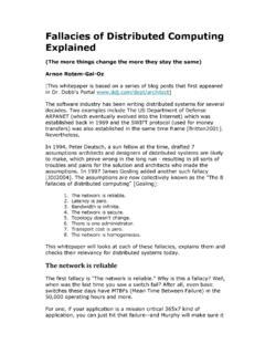
3 For example, the expected performance might be received signal strength of -75 dBm across 85 percent of the coverage area. Naturally, final measurements and tuning are required to validate the design and optimize most existing DAS installations are configured to accommodate single input/single output (SISO) connectivity, it is also possible to accommodate multiple-input multiple-output (MIMO) operation for Long Term Evolution (LTE) by using a second RF feed and interleaving access points along a transmission line or collocating parallel SyStemS . This action is illustrated in Figure 1 as Side B. Figure 1. diStributed antenna systemsSide A700 LAWS over coaxSecond channel for MIMOH ybrid fiber/copperPCSSide BAPAPAPAPAPAPAPAPAPAPAPAPBTS #1 BTS #2 BTS #3 BIUPATCHPANELDC POWERLOCAL RFAMP(S)LOCAL RFAMP(S)LOCAL RFAMP(S) daS configurationsFor indoor MIMO DAS it is sensible to divide the range of venues into line of sight (LOS) and non-LOS applications. A LOS venue might be a large football stadium or basketball arena while a non-LOS venue would likely be an office building or a shopping a LOS venue, there are at least two options for deploying a DAS.
4 If a 2x2 system will provide acceptable capacity improvements, and cross polarized antennas are available at the DAS node as well as at the mobile, then a dual polarization MIMO DAS should Small CellS and diStributed antenna SystemsalCatel-luCent White paper2provide a twofold improvement in capacity. If dual polarization antennas are not an option, then it is possible to sectorize the venue and achieve gains that scale with the fractional increase in the number of support MIMO using passive DAS, two parallel subsystems/layers need to be installed, and a minimum of 3-5 feet of separation must be deployed between the two sets of interior antenna arrays to gain maximum efficiencies for MIMO technology. This said, deployment of MIMO with active DAS will be noticeably different, as the RF amplifiers are local to the antennas. Configuration of MIMO with active DAS will vary by to interference plus noise ratio (SINR) is arguably the most important variable in designing a MIMO DAS network (this assumes the RF scattering environment is suffi-ciently rich).
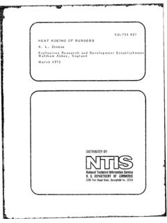
5 A high SINR supports higher modulation rates and it improves MIMO gains. In non-LOS venues, MIMO DAS can take several topological 2 illustrates that a 2x2 MIMO DAS deployment can require much more infrastruc-ture as a SISO system , but this again varies significantly by DAS design (for example, active versus passive, or how the RF/ antenna distribution is designed using active DAS).Figure 2. Typical MIMO configurations in non-LOS applications using passive DAS MIMO traditional DASRURUHEeNBDistributed MIMO DASF loor1 Floor2 Floor3 Floor4 RURUHEeNB It is anticipated that future DAS equipment will begin to represent an amalgam of existing DAS and Small CellS , bringing with it some of the Small CellS attributes discussed below. In particular, manufacturers all agree that significant savings could be attained by reducing the equipment required at the head end, further minimizing distribution costs through use of Ethernet, and lowering the backhaul costs as much as introduCtion to Small CellSSmall CellS represent wireless access points that are today usually dedicated to 1 to 2 regulated wireless bands (for example, AWS plus PCS, or 2600 MHz plus 1800 MHz), and perhaps Wi-Fi.
6 They can be designed to support many bands and any of the com-mon generational technologies (2G, 3G, 4G), but they are usually focused on a particular mobile operator s specific network requirements to curb product costs. Because of this, Small CellS today are usually not considered in instances where neutral host operation is a requirement. But this is not to say that future Small CellS cannot support requirements for multi-operator core networks (MOCN) or multi-public land mobile networks (multi-PLMN), in which two or more providers share a mobile network operating on common bands, because they CellS and diStributed antenna SystemsalCatel-luCent White paper3 Similar to DAS, Small CellS consist of a fiber optic transport network and multiple wire-less access points. Unlike DAS, a fiber optic transponder (BIU) bridging the base station RF signals to fiber is not required Small CellS are attached either directly to the BTS baseband unit, or to the wireless core using a common 3G gateway or evolved packet core (EPC) in the case of LTE.
7 When they are attached to the baseband unit (BBU), they employ the common public radio interface (CPRI). When they attach to the core using a 3G gateway or EPC, they employ on the chosen network architecture, Small CellS can appear as a single cell site sector (in the case of CPRI-connected Small CellS ), or as a very Small (pico) cell site. The selection of which configuration to use depends on the application as well as engineering 3. CPRI-connected Small CellS using PCS as the example band Side ASecond channel for MIMOH ybrid fiber/copperPCS over CPRISide BBTSPATCHPANELDC POWERLOCAL DIST PANELLOCAL DIST PANELLOCAL DIST PANELSC APSC APSC APSC APSC APSC APSC APSC APSC APSC APSC APSC APCPRI-connected Small CellS contain an RF transceiver and antenna . They are very similar to DAS in application, as both present themselves as one cellular sector. And, depending on network design, they can appear as one long antenna segment. However, a BIU is unnecessary in a Small CellS network because Small CellS are either directly attached to the BBU, a Small CellS gateway (in the case of 3G), or an EPC (in the case of LTE).
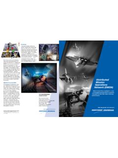
8 Small CellS advantageS uSing ethernet ConneCtivityEthernet-connected Small CellS are quite different from DAS. These types of Small CellS contain the antenna , RF transceiver, and baseband modulation (that is, BBU). From a network architecture perspective, Ethernet-connected Small CellS resemble a radio access network (RAN) of many cell sites. In the case of 3G, the addition of many access points is masked by the 3G gateway (a set of server functions containing security, timing, and radio control). In the case of LTE, the Small CellS terminate at the EPC. The advantage to using Ethernet-connected Small CellS is that they can be terminated anywhere in a network, irrespective of the remaining RAN. This eliminates the need to have the BTS and/or RF transceiver close to the Small CellS location, making Small CellS use much more CellS and diStributed antenna SystemsalCatel-luCent White paper4 Figure 4. Ethernet-connected Small CellS IuH or S interfaceHomeEnterpriseStadium3G GWOR 4 GEPCGIGEETHERNETSWITCHDC POWERLOCAL PWR DIST PANELLOCAL PWR DIST PANELSC APSC APSC APSC APSC APSC APSC APSC AP The capacity of Small CellS varies based on the following: With CPRI-connected Small CellS , the capacity is generally limited to the per-sector performance of the BBU it is connected to and the airlink (whichever exhausts first).
9 With Ethernet-connected Small CellS , the capacity is generally limited by the backhaul and its connections or the airlink (whichever exhausts first). In all instances DAS included limits could be experienced in the regard to the above, CPRI-connected Small CellS largely mimic the limits of DAS, while Ethernet-connected Small CellS are in a league of their Ethernet-connected Small CellS represent a standalone base station of sorts, they can provide significant capacity. By example, a gigabit Ethernet-connected Small cell has 1000 Mb/s at its disposal (assuming no further limitations in the network). Based on use of 4x4 LTE MIMO at the downlink, four 300 Mb/s unicast streams can be delivered simultaneously to a set of users, or 64 15 Mb/s can be delivered simultaneously (discounting any overhead for simplicity in discussion). By comparison, the total sector throughput of a single BTS in the same scenario would be 300 Mb/s. If they were to serve the identical footprint, a set of 10 Small CellS would then offer 3000 Mb/s worth of capacity as opposed to 300 Mb/s worth of capacity of a single sector.
10 Of course, this example ignores many real-world realities in order to draw the comparison as clearly as a mobility perspective, both CPRI-connected Small CellS and DAS are quite similar; the access points represent a single sector in which the user is located. The opposite is true with Ethernet-connected Small CellS in which users appear to roam among a set of Small cell of Small CellS verSuS daSThe cost to implement Small CellS or DAS very much depends on application topology and expected performance has modeled many types of networks using both Small CellS , active DAS and passive DAS, and aside from the usual variations in equipment cost, has found the following variables to impact total cost of ownership (TCO) significantly: Desired capacity/total throughput and bandwidth per user: The ability to satisfy many users with a single radio sector versus multiple active radios determines whether the system can be passive or CellS and diStributed antenna SystemsalCatel-luCent White paper5 Building configuration and location of risers: Depending on architecture chosen, labor to install feeders and drops can vary widely.