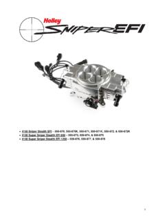
Transcription of Sniper EFI Fuel Kits P/N 526-5/526-8 (20 ft. hose) & 526-7 ...
1 Sniper EFI fuel kits P/N 526-5/526-8 (20 ft. hose) & 526-7 (40 ft. hose). fuel SYSTEM INSTALLATION. DANGER! Take precautions to ensure that all fuel components are away from heat sources, such as the engine or exhaust pipes. A fire or explosion hazard could cause serious injury or death! DANGER! Before disconnecting or removing fuel lines, ensure the engine is cold. Do not smoke. Extinguish all open flames. An open flame, spark, or extreme heat near gasoline can result in a fire or explosion causing property damage, serious injury, and/or death. DANGER! Never get under a vehicle supported only by a jack.
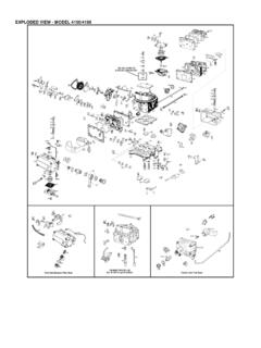
2 Serious injury or death can result from vehicles falling off of jacks. Before working underneath a vehicle, support it solidly with jack stands. Parts Identification ITEM DESCRIPTION QTY SERVICE PART. 1A Universal Electric fuel Pump 1 12-920 (526-5 & 526-7 ). 1B Sniper EFI fuel Pump 1 19-300 (526-8). 2A 20 FT - 3/8 EFI Vapor Guard Hose 1 = 20 ft. 752066 ERL (526-5 & 526-8). 2B 20 FT - 3/8 EFI Vapor Guard Hose 2 = 40 ft. 752066 ERL ( 526-7 ). 3 Post fuel Filter 10 micron 1 Holley P/N 562-1 or NAPA P/N 3482. 4 Pre fuel Filter 20 micron 1 NAPA P/N 3033. 5 Vapor Guard Hose Clamp, Size 8 11 750006 ERL.
3 6A -6 ST. to 3/8 Vapor Guard Hose End 3 750166 ERL (526-5 & 526-8). 6B -6 ST. to 3/8 Vapor Guard Hose End 4 750166 ERL ( 526-7 ). 8 fuel Cuff (240MM long) 1 12-719. 9 9/16 Dowty Seal (pack of 2) 1 178109 ERL. 10 Sniper -6 AN Bulkhead Nut 2 24506063. 11 Sniper 90 -6 AN Bulkhead Fitting 1 23506063. 1A 1B 2 3 4. 5 6. 8 9 10 11. fuel Pump and Filter Installation NOTE: If you have dual fuel tanks, you must purchase Holley PN 534-38. The following section covers the installation of the in-line pump as well as the pre and post filters. The fuel pump MUST be mounted lower than the lowest part of the fuel tank, and as close to the tank as possible.
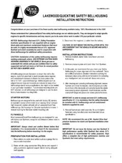
4 The fuel tank must also be properly vented. 1. Use Figure 1 below as a reference for the orientation and location of the fuel system components: Figure 1 526-7 shown above 2. Mount the electric fuel pump as close to the fuel tank outlet as possible with the bracket provided. This will reduce fuel pump prime time, resulting in quick engine starts. 3. There are two filters included with this kit. The pre-filter (Item 4) MUST be installed between the fuel tank and the fuel pump inlet (unless an in-tank pump is used in place of the pump in this kit). The purpose of this filter is to protect the fuel pump from particles of dirt or other foreign material.
5 The filter should be installed with the arrow on the filter pointing in the direction of the fuel flow. 4. The post- fuel filter (Item 3) should be installed between the electric pump outlet and TBI unit. This is a 10 micron EFI filter. Position the filter, so the fuel hoses can be routed without kinks or sharp bends. The filter should be installed with the arrow on the filter pointing in the direction of the fuel flow (Figure 2). Figure 2. WARNING! Ensure both filters are installed in the proper direction. A flow direction arrow is printed on the side of the filter to indicate the direction of fuel flow.
6 Failure to do so will result in a system malfunction. Return Line Bulkhead Fitting Installation The Sniper EFI system requires a return fuel line to the fuel tank. The 526-7 kit includes the hose and fittings necessary for a return line installation on most vehicles. 526-5 is intended to be used on some late model vehicles that were originally equipped with a throttle body injection system. These vehicles may already have a feed or a return line to the fuel tank that can be utilized. The return line must not present a pressure restriction to the return fuel flow. There should never be more than approximately 3 PSI of pressure in the return line.
7 A line that is too small, or has restrictions will cause tuning problems with the system. DANGER! Do not use the vapor canister lines as a fuel return line. Possible fuel leaks may create a fire or explosion hazard, causing serious injury or death. DANGER! Proper installation of the fuel return line will necessitate complete removal of the fuel tank. This work should be done by a fuel tank specialist, who regularly does this work and is familiar with safety regulations and precautions necessary to do this work. If a person attempts this work, who is not familiar with the safety regulations and precautions, an explosion hazard may result causing serious injury or death.
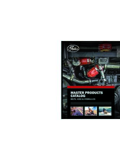
8 1. Choose an ideal location for the bulkhead fitting to be installed. The fitting must be installed through a flat surface where the nut can be tightened from the bottom. It must also be installed in a location where the fuel cuff will not interfere with the sending unit float. If possible, we strongly recommend removing, cleaning, and drilling into the sending unit. The fitting must be oriented as shown below in Figure 3. The item numbers from section are referenced. DANGER! IF DRILLING INTO TANK (RATHER THAN SENDING UNIT), HOLLEY RECOMMENDS HAVING YOUR TANK. PROFESSIONALLY CLEANED BEFORE DRILLING.
9 IF YOU CHOOSE NOT TO HAVE THE TANK PROFESSIONALLY. CLEANED, DRAIN THE TANK COMPLETELY, LET DRY, AND FILL WITH WATER. Figure 3. 2. Drill a 9/16 hole and debur. Remove all metal shavings and particles from tank. 3. Install bulkhead fitting with one Dowty Seal above the surface, and one below. 4. Screw bulkhead nut onto fitting from the bottom of the surface. Snug with a wrench. A spare bulkhead nut has been provided and will not be used in this installation. 5. Insert barbed end of a straight Vapor Guard hose end (Item 6) into an end of the fuel cuff (Item 8). 6. Slide hose clamp (Item 5) over fuel cuff and fitting and tighten to secure.
10 7. Screw fuel cuff assembly to bottom of bulkhead nut and snug with a wrench. Ensure bottom of cuff will be submerged in fuel as shown in Figure 3. Cuff can be trimmed if necessary. fuel Line Installation With the fuel pump, filters, and bulkhead fitting all in place. You are now ready to install the fuel lines. Some connections will use hose clamps (Item 5), while others will use AN hose ends (Item 6). These connections are noted in Figures 1 & 3. Be sure to read and thoroughly understand all steps, notes, and hose assembly instructions (Section ) below before proceeding with the fuel line installation.