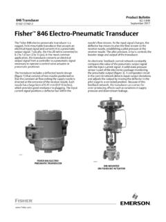
Transcription of Soft-start/quick exhaust valve MS6-SV--D-10V24 - Festo
1 EnOperating instructions80437861702a[8043788]Soft-st art/quick exhaust 1702a EnglishOriginal instructionsIdentification of hazards and instructions on how to prevent them:DangerImmediate dangers which can lead to death or serious injuriesWarningHazards that can cause death or serious injuriesCautionHazards that can cause minor injuriesOther symbols:NoteMaterial damage or loss of functionRecommendations, tips, references to other documentationEssential or useful accessoriesInformation on environmentally sound usageText designations: Activities that may be carried out in any order1. Activities that should be carried out in the order stated General lists Result of an action/References to more detailed 1702a English3 Table of contents1 About this safety directives and function in accordance with EN ISO for product of skilled cause failures (CCF) of applications and sections and and for activation and 1 and 1702a and spare 1702a English51 About this documentFor all available product documentation safety informationNoteFailure of the safety functionCommon cause failures, subsequently called CCF, cause the failure of the safety func tion, since in this case both channels in a two-channel system fail measures to control the CCFs are not observed, the safety function of the Soft-start/quick exhaust valve can be impaired.
2 Make sure that the described measures for managing the CCFs are observed( Common cause failures (CCF) and Safety characteristics).NoteFailure of the safety functionFailure to observe the technical data can result in the failure of the safety function. Observe the technical data ( 15 Technical data). 1702a usageThe hereafter called the MS6-SV-D, is an electro - pneumatic soft-start/quickexhaust valve designed in accordance with EN ISO 4414. The MS6-SV-D is intended for the followingpurposes: Pressure release and pressure switch-on in higher levels in accordance with EN ISO 13849-1 Gradual pressure build-up in pneumatic piping systems and terminals in industryThe MS6-SV-D has two safety functions: pressure release protection from unexpected start-up (non-switching)The MS6-SV-D is designed to change from the normal position to the switching position when bothcoils are energised simultaneously.
3 The normal position is achieved by switching off both MS6-SV-D is intended for installation in machines or automation technology systems and must beused exclusively as follows: in an industrial environment within the limits defined by the technical data ( 15 Technical data) in its original condition, without unauthorised modifications in perfect technical condition in accordance with the specifications of these operating misuseThe following foreseeable misuses are among those not approved as intended use: use outdoors use as control for coupling/braking combinations on mechanical presses bypassing of the safety function use in reversible operation (using supply air instead of exhaust air, and vice versa) vacuum operationNoteIn the event of damage caused by unauthorised manipulation or use other than thatintended, the guarantee is invalidated and the manufacturer is not liable for 1702a directives and standardsVersion status2006/42/ECEN 1037 + A1:2008-04EN ISO 4414:2010-11EN ISO 13849-1:2015-12EN ISO 13849-2:2012-10 Tab.
4 1 Standards/directives specified in the function in accordance with EN ISO 13849 The MS6-SV-D has features that permit achievement of a performance level e for the following safetyfunctions: pressure release protection from unexpected start-up (non-switching) in accordance with EN 1702a English3 Requirements for product use Make the operating instructions available to the following persons: design engineer of the machine or system installer of the machine or system maintenance staff of the machine or system Keep these operating instructions for the entire product lifecycle. Take into consideration the legal regulations applicable for the location as well as the followingpoints: Regulations and standards Regulations of the testing organisations and insurers National of skilled personnelThe following steps must only be carried out by qualified specialists: Installation Installation Commissioning Maintenance RepairThe qualified personnel must be familiar with the following points.
5 Electrical and pneumatic control technology applicable regulations for operating safety engineering systems applicable regulations for accident prevention and occupational safety documentation for the productNoteWork on safety-related systems may only be carried out by qualified personnel familiarwith safety cause failures (CCF)To achieve the desired performance levels, the applicable measures against CCF must be implementedin accordance with the specifications of EN ISO 1702a valueThe PFHd value depends on the version of the MS6-SV-D and the annual actuationrate (nop).PFHd value [10-7]2 Actuation rate (nop) [104/a]Fig. 1 PFHd value 1702a EnglishPFHd value [10-8]2 Actuation rate (nop) [104/a]Fig. 2 PFHd value of applications and certificationsThe MS6-SV-D is a safety device in accordance with the Machinery standards and test values, which the MS6-SV-D must comply with and fulfil, can befound in the section Technical data.
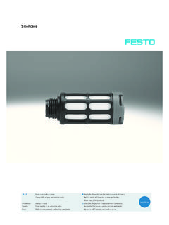
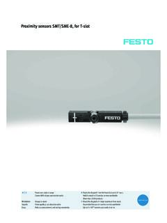
6 The product-relevant EC directives and standards can be found inthe declaration of and declaration of conformity for the MS6-SV-D ( ). may only be conducted with the parts listed in the spare parts catalogue ( ). Opening the housing is prohibited. Contact your regional Festo contact person if you have technical 1702a English114 Control sections and connections123456789aJaA1 Coil connection pilot valve V12 Coil connection pilot valve V23 pneumatic port 2(output pressure p2)4 Pressure indicator (optional)5 Proximity switch S26 Proximity switch S17 pneumatic silencer mounted at pneumaticport 3 ( exhaust p3)8 Slot for proximity sensor S39 valve bodyaJPneumatic port 1(operating pressure p1)aAFlow control screw for soft-start functionFig. 3 Operating elements and 1702a English5 Application and MS6-SV-D is equipped with proximity sensors, which are intended for diagnostics of the internalvalves.
7 Performance level d/e in category 3 can be achieved by using proximity sensors S1 and level e in category 4 can be achieved by using an additional proximity sensor principleItemPort 1 (operating pressure p1)1pneumatic Fig. 3 Port 2 (output pressure p2)2 Port 3 ( exhaust p3)3 Coil connection pilot valve V1V1electricalCoil connection pilot valve V2V2 Proximity switch S1S1 MagneticProximity sensor S2S2 Proximity sensor S31)S3 Flow control valveDRmechanical1) 1702a logicIn the normal position (completely exhausted MS6-SV-D), the pilot valves V1 and V2 are not both pilot valves are actuated, the MS6-SV-D switches first to the switching position 1 and then,when the switch-through pressure is reached, automatically into switching position 2 ( Fig. 4).V1V2S1S2S3MS6-SV-DVoltage [V]Switching positionStatus00111 Normal positionConnection 1 closed, passage from connection 2 to 3 opened240011 Normal position, optional testing condition ( Ta b.
8 6 )Port 1 closed, passage from port 2 to 3 opened024101 Normal position, optional testing condition ( Ta b . 6 )Reduced flow via flow control valve from port 1 to 2, passage from port 2 to 3 opened2424001 Switching position 1 Reduced flow via flow control valve from port 1 to 2,passage from port 2 to 3 closed2424000 Switching position 2 Full flow from port 1 to 2; passage from port 2 to 3 closedTab. 3 Switching exhaust valve , 4 Circuit symbol for the 1702a characteristicsSwitching characteristics of the internal valves of the MS6-SV-D. The normal position bled off issensed by means of the proximity sensors. Switching logic ( Switching logic).Operating pressure p1 Output pressure p2 Pilot valve V21 = 24 V, 0 = 0 VPilot valve V11 = 24 V, 0 = 0 VProximity switch S11 = 24 V, 0 = 0 VProximity switch S21 = 24 V, 0 = 0 VProximity sensor S31 = 24 V, 0 = 0 V11 TimeFig.
9 4 Input and output switching characteristics in normal statusProximity switch response times1)Switching onSwitching offt1 Depending on p1, flow control valvesetting and system volume at of 4 s after signal at of 4 s after signal drop at of 4 s after signal at of 4 s after signal drop at signal at V1 and on p1, flow control valvesetting and system volume at of 5 s after signal drop at V1 andV2. Depending on system volume at )After the response time the signals are applied maximum specified response times must be considered in the diagnostics. These response times are normally 5 Proximity switch response 1702a pressureThere is a flow control screw in the end cap. The flow control screw can be used to generate a gradualpressure build-up of output pressure p2 ( Fig. 10). The flow and thus the pressure rise can be adjus ted by turning the flow control screw. When the output pressure p2 reaches about 50 % of the operat ing pressure p1, the maximum flow rate is of p2 to p1 [%]2 Filling time tFig.
10 5 Switch-through pressure tolerance 1702a English6 Recommendation for activation and diagnosticsIf the results of activation and the sensor signals S1, S2 and S3 are not plausible, carryout the following measures:1. Switch off voltage to pilot valves V1 and Output error Prevent new and status transitionsDiagnostics at each switching voltage to pilot valves V1 and = 1; V2 = edge change at proximity sensors S1 and = 1 0; S2 = 1 0 Optional, when using a third proximity switch S3 edge change at proximity sensor = 1 0 Corresponding response times ( Fig. 4).Diagnostics at each resetting to the normal off voltage to pilot valves V1 and = 0; V2 = edge change at proximity sensors S1 and = 0 1; S2 = 0 1 Optional, when using a third proximity switch S3 edge change at proximity sensor = 0 1 Corresponding response times ( Fig. 4).Diagnostics in normal positionPay attention to forced switch on/off ( Safety characteristics).