Transcription of SOLID MECHANICS TUTORIAL – GEAR SYSTEMS
1 1 SOLID MECHANICS TUTORIAL gear SYSTEMS This work covers elements of the syllabus for the Edexcel module 21722P HNC/D Mechanical Principles OUTCOME 3. On completion of this short TUTORIAL you should be able to do the following. Describe the different types of gear SYSTEMS . Describe a simple gear train. Describe a compound gear rain. Describe three types of epicyclic gear boxes Solve gear box ratios. Calculate the input and outputs speeds and torques of gear boxes. Calculate the holding torque on gear box cases It is assumed that the student is already familiar with the following concepts. Angular motion. Power transmission by a shaft. All these above may be found in the pre-requisite tutorials . 2 1. INTRODUCTION A gear box is a device for converting the speed of a shaft from one speed to another.
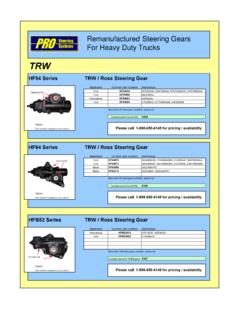
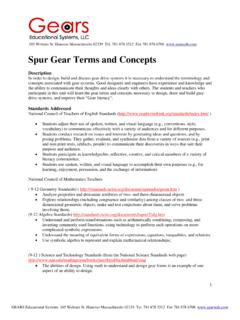
2 In the process the torque T is also changed. This can be done with pulley and chain drives but gears have advantages over these system . A good example is that of winch in which a motor with a high speed and low torque is geared down to turn the drum at a low speed with a large torque. Similarly, a marine engine may use a reduction gear box to reduce the speed of the engine to that of the propeller. Other examples are motor vehicles, lathes, drills and many more. The diagram shows a typical winch that has a reduction gear box built inside the drum. Figure 1 This TUTORIAL is not about the design of gears but it should be mentioned that there are many types of gears, each with their own advantages. Here are some examples. Figure 2 Gears are wheels which mesh with each other through interlocking teeth. Rotation of one wheel produces rotation of the other with no slip between them.
3 The shape of the gear teeth is important in order to produce a smooth transfer of the motion. The most common shape is the INVOLUTE gear form but it is not our task to study this here. The design of the gear teeth also affects the relative position of one gear to another. For example bevelled gears allow the axis of one gear to be inclined to the axis of another. Worm gears convert the motion through 90o and so on. The design also affects the friction present in the transfer. 3 2. BASIC gear BOX THEORY Consider a simple schematic of a gear box with an input and output shaft. Figure 3 gear BOX RATIO The ratio of the gear box is defined as 21 NNSPEED OUTPUTSPEED N is usually in rev/min but the ratio is the same whatever units of speed are used. If angular velocity is used then 21 SPEED OUTPUTSPEED TORQUE AND EFFICIENCY The power transmitted by a torque T Nm applied to a shaft rotating at N rev/min is given by =.
4 In an ideal gear box, the input and output powers are the same so TNTN 60TN260TN2211222112211==== It follows that if the speed is reduced, the torque is increased and vice versa. In a real gear box, power is lost through friction and the power output is smaller than the power input. The efficiency is defined as: 11221122 TNTN60 x TN 2 60 x TN 2 InPower OutPower === Because the torque in and out is different, a gear box has to be clamped in order to stop the case or body rotating. A holding torque T3 must be applied to the body through the clamps. Figure 4 The total torque must add up to zero. T1 + T2 + T3 = 0 If we use a convention that anti-clockwise is positive and clockwise is negative we can determine the holding torque. The direction of rotation of the output shaft depends on the design of the gear box.
5 4 WORKED EXAMPLE 1. A gear box has an input speed of 1500 rev/min clockwise and an output speed of 300 rev/min anticlockwise. The input power is 20 kW and the efficiency is 70%. Determine the following. i. The gear ratio ii. The input torque. iii. The output power. iv. The output torque. v. The holding torque. SOLUTION 5 3001500 NNSPEED OUTPUTSPEED wise)(Anticlock Nm - T0 T ) antic (positive Nm 300 x 2000 14 x 60 T N2 OutPower x 60 T 60TN2 out Power kW 14 20 x In Power x Out power InPower OutPower clockwise) (Negative Nm 1500 x 2000 20 x 60 T N2 InPower x 60 T 60TN2 In Power 333112222211111===++=++============= 5 SELF ASSESSMENT EXERCISE 1. A gear box has an input speed of 2000 rev/min clockwise and an output speed of 500 rev/min anticlockwise. The input power is 50 kW and the efficiency is 60%.
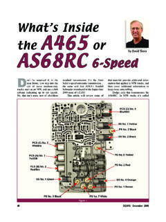
6 Determine the following. i. The input torque. ( Nm) ii. The output power. (30 kW) iii. The output torque. (573 Nm) iv. The holding torque. ( Nm clockwise) 2. A gear box must produce an output power and torque of 40 kW and 60 Nm when the input shaft rotates at 1000 rev/min. Determine the following. i. The gear ratio. ( ) ii. The input power assuming an efficiency of 70% ( kW) 6 3. TYPES OF gear TRAINS The meshing of two gears may be idealised as two smooth discs with their edges touching and no slip between them. This ideal diameter is called the Pitch Circle Diameter (PCD) of the gear . SIMPLE gear TRAIN. Figure 5 These are typically spur gears as shown in diagram 1. The direction of rotation is reversed from one gear to another. The only function of the idler gear is to change the direction of rotation.
7 It has no affect on the gear ratio. The teeth on the gears must all be the same size so if gear A advances one tooth, so does B and C. t = number of teeth on the gear . D = Pitch circle diameter. m = modem = D/t and this must be the same for all gears otherwise they would not mesh. m = DA/tA = DB/tB = DC/tC DA = m tA DB = m tB DC = m tC = angular velocity. v = linear velocity on the circle. v = D/2 The velocity v of any point on the circle must be the same for all the gears, otherwise they would be slipping. It follows that CCBBAACCBBAACCBBAACCBBAAt t t mt mt mt D D D 2D 2D 2D ======== or in terms of rev/min NA tA = NB tB = NC tC The gear ratio is defined as GR = Input speed/Output speed If gear A is the input and gear C the output, GR = NA / NC = tC/ tA 7 WORKED EXAMPLE A simple train has 3 gears. gear A is the input and has 50 teeth.
8 gear C is the output and has 150 teeth. gear A rotates at 1500 rev/min anticlockwise. Calculate the gear ratio and the output speed. The input torques on A is 12 Nm and the efficiency is 75%. Calculate the output power and the holding torque. SOLUTION GR = NA / NC = tC/ tA= 150/50 = 3 NA / NC = 3 NC = NA /3 = 1500/3 = 500 rev/min (anticlockwise) TA = 12 Nm P (input) = 2 NATA/60 = 2 x 1500 x 12/60 = 1885 W P (output) = P (Input) x = 1885 x = W Nm 27 500 x x 60 N2)60P(outputTCC=== TA + TC + T hold = 0 12 + 27 + T hold = 0 T hold = - 39 Nm (clockwise) SELF ASSESSMENT EXERCISE A simple gear train has 2 spur gears. The input gear has 20 teeth and the output gear has 100 teeth. The input rotates at 2000 rev/min clockwise. Calculate the gear ratio and the output speed. (5 and 400 rev/min anticlockwise) The input torque is 15 Nm and the efficiency is 65%.
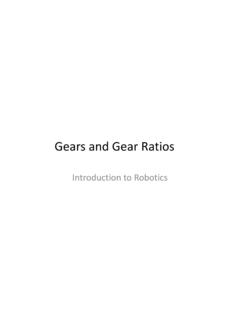
9 Calculate the output power and the holding torque. (2 042 W and Nm clockwise) 8 COMPOUND GEARS Compound gears are simply a chain of simple gear trains with the input of the second being the output of the first. A chain of two pairs is shown below. gear B is the output of the first pair and gear C is the input of the second pair. Gears B and C are locked to the same shaft and revolve at the same speed. Figure 6 The velocity of each tooth on A and B are the same so AtA = BtB as they are simple gears. Likewise for C and D, C tC = D tD. shaft, same on the are C and B gears Sincetttt x ttttt t x t t t t t t t t and t t CADBDACBCADBDBCADBCADBCD DAB BCACD DCAB BACD DCAB BA========== Since = 2 N then the gear ratio may be written as()() Gears B and D are the driven gears. Gears A and C are the driver gears.
10 It follows that: gear ratio = product of driven teeth/product of driving teeth This rule applies regardless of how many pairs of gears there are. 9 WORKED EXAMPLE Calculate the gear ratio for the compound chain shown below. If the input gear rotates clockwise, in which direction does the output rotate? Figure 7 gear A has 20 teeth gear B has 100 teeth gear C has 40 teeth gear D has 100 teeth gear E has 10 teeth gear F has 100 teeth SOLUTION The driving teeth are A, C and E. The driven teeth are B, D and F gear ratio = product of driven teeth/product of driving teeth gear ratio = (100 x 100 x 100)/ (20 x 40 x 10) = 125 Alternatively we can say there are three simple gear trains and work ot the ratio for each. First chain GR = 100/20 = 5 Second chain GR = 100/40 = Third chain GR = 100/10 = 10 The overall ratio = 5 x x 10 = 125 Each chain reverses the direction of rotation so if A is clockwise, B and C rotate anticlockwise so D and E rotate clockwise.