Transcription of Sound Logic Encoder Interface - rogersmachine.net
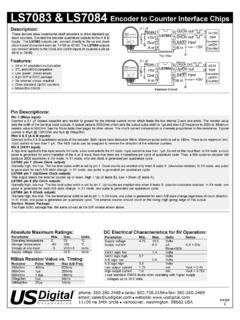
1 Sound Logic Encoder Interface 4-axis parallel port Encoder Interface For Mach2/3 CNC control software Closed loop operation for Servo and Stepper systems General User s GuideSound Logic James Cullins3454 Sprindletree , Tx. 76051 INFORMATIONC opyright and TrademarksCopyright 2005 by Sound LogicDisclaimers of liabilitySound Logic or James T. Cullins assumes no responsibility or liability for any damage done to persons, PC, Geckodrives, encoders, or any other electroniccomponent used in conjunction with this Sound Logic Encoder Interface includingmaterial in process.
2 Also, loss of time or loss of work incurred. Use at your own risk. 4-axis Mach2/3 Encoder InterfacePurpose:To Interface a second PCI parallel port card from a PC running Mach software with upto 4 individual Encoder /Gecko drive inputs. Which will display the data in a DRO on aMach screen. Giving the user, real time data count feedback from each encoderthereby displaying the actual position of each axis. And used with provided Macropumpfor this particular purpose, alerts the user with an LED next to the offending axis andprompts a sonalert device if used in the event of a step/count discrepancy.
3 Themachine will be halted in feedhold status. A is also supplied that isdesigned for this purpose as well and both are sent via Email with also be used as a stand-alone device to accept Encoder data and relay it to PC foruse solely as DRO for all types of Encoder data input with Mach software. Which would require, only one PCI parallel port card, Namely, Port1. Or simply used as8 general use inputs instead of Encoder inputs. Inputs such as MPG s, Probes, OEMtriggers etc. Plus 4 software controlled onboard relays rated 125 VAC and 15 to be used in conjunction with Sound Logic PC-2-route breakout on 115/220 volts at 60 Hz.
4 Note: 115 volts- JP1 and JP2 are installed. 220volts must have a jumper installed between JP1-1 to JP2-2. And existing jumpers mustbe :!PCB!Fr4 Material!Solder mask on both sides!Silkscreen legend on topside!Plated through holes!Isolated 5 volts and grounds for the Encoder Interface parallel port IO!All outputs are buffered!Operational when Mach is in reset to provide the user Encoder DRO positionfor manual machining operations. !4 onboard relays rated 125 volts AC at 15 ampsto control spindle, coolant, vacuum pump etc.
5 Via M-codes in Mach software. Coupledwith Sound Logic PC to route Breakout board relay control jumpers will equal 8controllable outputs in total. Connectors:J1 (X axis)+5v Encoder +5vNote 1: Any axis J1 connector notXAEncoder AUsed with a Gecko may be usedXB Encoder BFor general purpose inputs on GND Encoder GndA & B terminal. The optical Isolator associated with an inputJ2 (X Gecko Encoder inputs)used for general purpose mayGnd Gecko GndNOT be used if anyone of the XAGecko Encoder A inputencoder inputs are wired to XBGecko Encoder B inputA Gecko drive s Encoder (Y axis)All the inputs except J18-1 has +5v Encoder +5vcomparators on them set for YAEncoder A VCC to provide good noiseYB Encoder Encoder GndJ2 (Y Gecko Encoder inputs)J16 General use inputGnd Gecko GndYAGecko Encoder A inputYBGecko Encoder B inputJ1 (Z axis)
6 J17 General use input+5v Encoder +5vZAEncoder AZB Encoder BGND Encoder GndJ18 General use input J2 (Z Gecko Encoder inputs)Note: J18-1 does not have a comparatorGnd Gecko Gndassociated with its input. ZAGecko Encoder A inputZBGecko Encoder B inputJ1 (A axis)+5v Encoder +5vAAEncoder AAB Encoder BGND Encoder GndJ2 (A Gecko Encoder inputs)Gnd Gecko GndAAGecko Encoder A inputABGecko Encoder B inputConnectors: J11 Connected to second parallel portPin 1 K1 relay out J12 Pin 2 Encoder /general purpose input see Note1 Pin 3 Encoder /general purpose input see Note1 Pin 4 Encoder /general purpose input see Note1 Pin 5 Encoder /general purpose input see Note1 Pin 6 Encoder /general purpose input see Note1 Pin 7 Encoder /general purpose input see Note1 Pin 8 Encoder /general purpose input see Note1 Pin 9 Encoder /general purpose input see Note1 Pin 10 Input 1/MPG1 A to J16-2 Pin 11 Input 2/MPG1 B to J16-1 Pin 12 Input 3/MPG2 A to J17-1 Pin 13
7 Input 4/MPG2 B to J17-2 Pin 14K2 relay J13 Pin 15 Probe/Switch (pulled up to +5v) J18-1 & J18-2 = GNDPin 16K3 relay J15 Pin 17 Charge pump / K4 relay J15 Pin 18-28 GNDJ9 (mode)CP uses charge pumpNCP no charge pumpA special cable can be connected (see note 2) from the MODE jumper on the encoderinterface to the MODE jumper on the Sound Logic breakout board and use the chargepump from the breakout board for both boards. This provides one more relay out (K4) for other vac / 220 vacFor 115vac JP1 and JP2 are installed, use as isFor 220vac A jumper from JP1-1 to JP2-1 must be installed and the two existingjumpers for 115 vac operation must be removed.
8 Note 2:J9-1 J9-2 Red jumper between J9-1and J9-2 is for charge pump on output Red jumper between J9-2 and J9-3 is for no charge pump and output 4 may beused in the same manner as output 1,2 and 3. Typical wiring for use with a Gecko servo-drive, To use with other typesof drives such as stepper-type that require no feedback, connection to theencoder is all that is required. And is the same basic configuration for anytype of 5 VDC input device MPG s, OEM triggers, Probes for installing second PCI parallel port in Windows XPStep 1.
9 Remove power from PC and open enclosure. Install PCI parallelport card in any available PCI slot. Replace screw and secure 2. Boot PC, Windows will automatically find the new hardware andinstall a driver for it. If not, the card should come with it s own softwaredriver on included disc. Install from the OEM disc 3. Mach will need to know the address of this port to communicatewith it. It will need be entered into the Config/ports and pins/ port setupand axis selection menu in Mach software. To find the address of thenewly installed second parallel port, simply navigate to the hardwareprofiles in Windows XP as follows:Click: Start/Control Panel/System/Hardware/Device Manager/Ports (Com &LPT)/ Printer Port LPT/ window like the one below should be displayed.
10 The first line will be theprimary parallel port and the second line should correspond to the secondparallel port. The four digits in the box are what is needed to be enteredinto Mach config Ports and pins menu. Mach will automatically change itto 0x778" when the address is saved/Applied. Also on the same menu inMach, place a check in the Enable port2" and Pins 2-9 as inputs boxes. Will be one of these. Typical screen configuration:On the following pages are displayed screenshots with suggested configurations forMach software using the Sound Logic Encoder Interface .