Transcription of span tables
1 ROSS Engineers have prepared these tables for use by people skilled in the design and specification of the type of structures covered. ROSS Engineers accepts no responsibility for misinterpretation of the information provided or omissions. Users should satisfy themselves as to the suitability of the span tables for their applications 21 Econo Place, Silverdale, NSW 2752 P 1300 132 787 F 02 4774 2679 SPAN tables 1 Contents Introduction .. 2 Australian Standards .. 2 design Loadings .. 2 Base Loads .. 2 Wind Loads .. 2 Ultimate Limit State .. 2 Serviceability Limit State .. 2 Serviceability Deflection Limits .. 2 Roof Pitch .. 3 Posts .. 3 Construction Notes .. 3 General .. 3 structural aluminium .. 3 Material Section Properties for 100 x 50 ALYSPAN Beam.
2 4 Material Section Properties for 150 x 50 ALYSPAN Beam .. 5 Connections Schematics .. 6 Standard Connections .. 6 Wind Class .. 7 Regional Wind Speed: .. 7 design Gust Wind Speed for Non-Cyclonic Regions A & B .. 7 Pressure Coefficients: .. 7 Case 1 .. 7 Case 2 .. 8 Wind Pressures: .. 8 Span tables for Case 1: Maximum Building Height = m .. 9 Span tables for Case 2: Maximum Building Height = m .. 13 design Certificate .. 17 2 Introduction These span tables have been prepared for the use of Quickbuilt Systems ALYSPAN structural aluminium Beam for attached patio, awning, and carport designs only. For the purposes of these tables , roofs are deemed attached to an existing approved dwelling. Australian Standards The structural sections comply with the following Australian Standards.
3 O AS 2002 structural design actions General Principles o AS 2002 structural design actions Permanent imposed and other actions o AS 2002 structural design actions Wind actions o AS 4055 2006 Wind Loads for Housing o AS 1664 1997 aluminium Structures All other proprietary products to be in accordance with the manufacturers specifications. design Loadings Base Loads o Dead Load (DL) - kPa Only roof sheeting is allowed for. o Live Load (LL) ( + ) kPa where A is the roof tributary area in m2. Span tables are designed for non-trafficable roofs Wind Loads o Span tables have been designed for the following wind classification regions: N1, N2, N3, N4, N5 Where: Wu = ultimate wind load (upwards or downwards) Ws = serviceability wind load (upwards or downwards) Ultimate Limit State o DL + LL o DL o DL + Wu (upwards) o DL + Wu (downwards) Serviceability Limit State o DL + Ws (upwards) o DL + Ws (downwards) Serviceability Deflection Limits o Dead Load: Span/300 o Wind Load: Span/300 3 Roof Pitch Use recommended minimum roof pitches as specified by roof sheet supplier.
4 The span tables in this report allow for a maximum roof pitch of 5 . Posts These span tables are designed for a minimum post size of 50 x 50 x mm and up to a maximum height of m. Construction Notes General The following guidelines shall be adhered to at all stages of construction: o Verify all setting out dimensions with architect. Contractor shall verify all dimensions, elevations, property lines etc. on the job site. o Do not obtain dimensions by scaling the structural elements. o Should any ambiguity, error, omission, discrepancy, inconsistency or other fault exist or seem to exist in the contract documents, immediately notify in writing to the superintendent. o Maintain the structure in a stable condition during construction. No part shall be overstressed. Temporary bracing shall be provided by the contractor to keep the works stable at all times.
5 O All workmanship and materials shall be in accordance with the requirements of current SAA codes and the by-laws, ordinances or other requirements of the relevant building authorities. o Where patio covers are to be installed on an existing patio slab, the slab shall be in good condition. Posts shall be located where the slab is free from cracks, deterioration, honeycombing or where other poor workmanship exists. o It shall be the responsibility of the contractor to shore and brace as required. structural aluminium o All workmanship and materials to be in accordance with AS 1664 except where varied by contract documents o structural aluminium shall be erected plumb and true to line. Temporary bracing shall be installed and shall be left in place until other means are provided to adequately brace the structure.
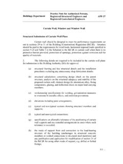
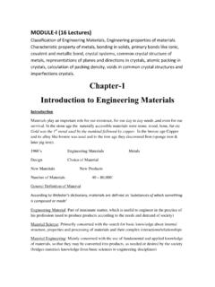
6 4 Material Section Properties for 100 x 50 ALYSPAN Beam o Alloy: 6063 T6 o Ixx = mm4 o Iyy = mm4 o Area = 599 mm2 o Weight = kg/m 5 Material Section Properties for 150 x 50 ALYSPAN Beam o Alloy: 6063 T6 o Ixx = mm4 o Iyy = mm4 o Area = 759 mm2 o Weight = kg/m 6 Connections Schematics Refer to manufacturer for further details regarding brackets and fixings. Standard Connections 7 Wind Class Wind classifications have been chosen as per AS4055. The table below show the design wind speeds for wind classes N1 through to N6. Regional Wind Speed: design wind speeds where adopted from AS4055 design Gust Wind Speed for Non-Cyclonic Regions A & B Wind Classification design Gust Wind Speed (m/s) Regions A & B (Non-Cyclonic) Ultimate Limit State, Vu Serviceability Limit State, Vs N1 34 26 N2 40 26 N3 50 32 N4 61 39 N5 74 47 N6 86 55 Pressure Coefficients: Pressure coefficients were adopted from :2011 Appendix D -Table D8.
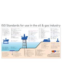
7 Case 1 For the awning pitched roofs, with the following parameters: o Minimum Awning Height (hc) = m o Maximum Building Height (h)= m Pressure coefficients for attached roof for worse case for 0-5 degree pitch Wind Direction Net pressure Coefficient (Cp,n) Uplift Downlift 8 Case 2 For the awning pitched roofs, with the following parameters: o Minimum Awning Height (hc) = m o Maximum Building Height(h) = m Pressure coefficients for attached roof for worse case for 0-5 degree pitch Wind Direction Net pressure Coefficient (Cp,n) Uplift Downlift Wind Pressures: Wind Pressures for Case 1: Maximum Building Height = m Wind Classification Ultimate Case Serviceability Case Regions A & B (Non-Cyclonic) Upward Pressure (kPa) Downward Pressure (kPa) Upward Pressure (kPa) Downward Pressure (kPa) N1 N2 N3 N4 N5 N6 Wind Pressures for Case 2: Maximum Building Height = m Wind Classification Ultimate Case Serviceability Case Regions A & B (Non-Cyclonic) Upward Pressure (kPa) Downward Pressure (kPa) Upward Pressure (kPa) Downward Pressure (kPa) N1 N2 N3 N4 N5 N6 9 Span tables for Case 1: Maximum Building Height = m Single Span No Overhang 100 x 50 mm ALYSPAN Beam Single Span No Overhang Max.
8 Adjacent Building Height = m W Maximum Allowable Span (mm) N1 N2 N3 N4 N5 1500 3700 3700 3100 2600 2200 1800 3500 3500 2900 2400 2100 2100 3300 3300 2700 2300 1900 2400 3200 3200 2600 2200 1800 2700 3000 3000 2500 2100 1700 3000 2900 2900 2400 2000 1600 3300 2800 2800 2300 1900 1500 3600 2700 2700 2300 1800 1400 3900 2700 2700 2200 1700 1300 4200 2600 2600 2100 1600 1300 4500 2500 2500 2000 1500 1200 150 x 50 mm ALYSPAN Beam Single Span No Overhang Max. Adjacent Building Height = m W Maximum Allowable Span (mm) N1 N2 N3 N4 N5 1500 5100 5100 4200 3600 3100 2000 4700 4700 3800 3300 2600 2500 4300 4300 3600 2900 2300 3000 4100 4100 3300 2600 2100 3500 3900 3900 3100 2400 1900 4000 3700 3700 2900 2300 1800 4500 3500 3500 2700 2100 1700 5000 3400 3300 2500 2000 1600 5500 3300 3100 2400 1900 1500 6000 3200 3000 2300 1800 1400 6500 3100 2900 2200 1700 1300 7000 3000 2800 2100 1600 1300 10 Span tables for Case 1: Maximum Building Height = m Single Span Up to 600mm Overhang 100 x 50 mm ALYSPAN Beam Single Span Max.
9 600 mm Overhang Max. Adjacent Building Height = m W Maximum Allowable Span (mm) N1 N2 N3 N4 N5 1500 3300 3300 2800 2500 2200 1800 3100 3100 2700 2300 2100 2100 3000 3000 2600 2300 2000 2400 2900 2900 2500 2200 1900 2700 2800 2800 2400 2100 1800 3000 2700 2700 2300 2100 1700 3300 2600 2600 2300 2000 1600 3600 2600 2600 2200 1900 1500 3900 2500 2500 2200 1800 1500 4200 2500 2500 2100 1800 1400 4500 2400 2400 2100 1700 1400 150 x 50 mm ALYSPAN Beam Single Span Max. 600 mm Overhang Max. Adjacent Building Height = m W Maximum Allowable Span (mm) N1 N2 N3 N4 N5 1500 4500 4500 3800 3200 2900 2000 4100 4100 3400 3000 2600 2500 3800 3800 3200 2800 2500 3000 3600 3600 3000 2600 2200 3500 3400 3400 2900 2500 2100 4000 3300 3300 2800 2400 1900 4500 3200 3200 2700 2200 1800 5000 3100 3100 2600 2100 1700 5500 3000 3000 2500 2000 1600 6000 2900 2900 2400 1900 1500 6500 2900 2900 2300 1800 1500 7000 2800 2800 2200 1800 1400 11 Span tables for Case 1: Maximum Building Height = Equal Continuous Span No Overhang 100 x 50 mm ALYSPAN Beam Equal Continuous Span No Overhang Max.
10 Adjacent Building Height = m W Maximum Allowable Span (mm) N1 N2 N3 N4 N5 1500 4900 4600 3600 2800 2300 1800 4700 4200 3200 2600 2000 2100 4400 3900 3000 2400 1900 2400 4200 3600 2600 2200 1700 2700 4100 3400 2500 2000 1600 3000 3900 3200 2400 1900 1500 3300 3700 3000 2300 1800 1400 3600 3600 2900 2200 1700 1300 3900 3400 2800 2100 1600 1300 4200 3300 2700 2000 1600 1200 4500 3200 2600 1900 1500 1200 150 x 50 mm ALYSPAN Beam Equal Continuous Span No Overhang Max. Adjacent Building Height = m W Maximum Allowable Span (mm) N1 N2 N3 N4 N5 1500 6900 6100 4700 3800 3000 2000 6200 5300 4100 3200 2600 2500 5700 4700 3600 2900 2300 3000 5200 4300 3300 2600 2100 3500 4800 3900 3000 2400 1900 4000 4500 3700 2800 2200 1700 4500 4200 3500 2600 2100 1600 5000 4000 3300 2500 1900 1500 5500 3800 3100 2300 1800 1400 6000 3600 3000 2200 1700 1300 6500 3500 2800 2100 1600 1300 7000 3300 2700 2000 1600 1200 12 Span tables for Case 1: Maximum Building Height = Equal Continuous Span Up to 600mm Overhang 100 x 50 mm ALYSPAN Beam Equal Continuous Span Max.