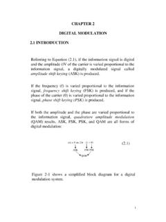
Transcription of Spatial Signal Processing (Beamforming)
1 Spatial Signal Processing (Beamforming)What Is Beamforming? Beamforming is Spatial filtering, a means of transmitting or receiving sound preferentially in some directions over others. Beamforming is exactly analogous to frequency domain analysis of time signals. In time/frequency filtering, the frequency content of a time Signal is revealed by its Fourier transform. In beamforming, the angular (directional) spectrum of a Signal is revealed by Fourier analysis of the way sound excites different parts of the set of transducers. Beamforming can be accomplished physically (shaping and moving a transducer), electrically (analog delay circuitry), or mathematically ( digital Signal Processing ).Beamforming Requirements Directivity A beamformer is a Spatial filter and can be used to increase the Signal -to-noise ratio by blocking most of the noise outside the directions of interest.
2 Side lobe control No filter is ideal. Must balance main lobe directivity and side lobe levels, which are related. Beam steering A beamformer can be electronically steered, with some degradation in performance. Beamformer pattern function is frequency dependent: Main lobe narrows with increasing frequency For beamformers made of discrete hydrophones, Spatial aliasing ( grating lobes ) can occur when the the hydrophones are spaced a wavelength or greater Simple Beamformer plane wave signalwave frontsdh1h20plane wave has wavelength = c/f, where f is the frequencyc is the speed of sound h1h1are two omnidirectional hydrophonesAnalysis of Simple Beamformer Given a Signal incident at the center C of the array: Then the signals at the two hydrophones are:where The pattern function of the dipole is the normalized response of the dipole as a function of angle.
3 T(ie)t(R)t(s = sind)(nn1 = =+= sindcossss)(b21)t(i)t(iiiee)t(R)t(s = Beam Pattern of Simple Beamformer-150-100-50050100150-60-50-40- 30-20-100 , degreesPattern Loss, dBPattern Loss vs. Angle of Incidence of Plane WaveFor Two Element Beamformer, /2 Element Spacing0-10-20-30-40-50-180-165-150-135- 120-105-90-75-60-45-30-15015304560759010 5120135150165 Polar Plot of Pattern Loss For 2 Element Beamformer /2 Element SpacingBeam Pattern of a 10 Element Array-150-100-50050100150-60-50-40-30-20 -100 , degreesPattern Loss, dBPattern Loss vs. Angle of Incidence of Plane WaveFor Ten Element Beamformer, /2 Spacing0-10-20-30-40-50-165-150-135-120- 105-90-75-60-45-30-150153045607590105120 135150165180 Polar Plot of Pattern Loss For 10 Element Beamformer /2 SpacingBeamforming Amplitude Shading Amplitude shading is applied as a beamforming function.)
4 Each hydrophone Signal is multiplied by a shading weight Effect on beam pattern: Used to reduce side lobes Results in main lobe broadeningBeam Pattern of a 10 Element Dolph-Chebychev Shaded Array-80-60-40-20020406080-60-50-40-30-2 0-100 , degreesPattern Loss, dBComparison Beam Pattern Of A 10 Element Dolph-Chebychev BeamformerWith -40 dB Side Lobes And /2 Element Spacing With A UniformlyWeighted 10 Element BeamformerDolph-ChebychevBeamformerUnifo rm BeamformerAnalogy Between Spatial Filtering (Beamforming) and Time-Frequency ProcessingGoals of Spatial SNR for plane wave signals in ambient ocean (distinguish between) plane wave signals arriving from different the direction from which plane wave signals are of Time-Frequency SNR for narrowband signals in broadband narrowband signals at different the frequency of narrowband signals.
5 1 0 Spatial angle Ambient noiseangular densityPlane wave at 1 Plane wave at 0 Narrow Spatial filter at 0f1f0 FrequencyBroadbandnoise spectrumSine wave at f1 Sine wave at f0 Narrowbandfilter at f0 Time-Frequency Filtering and BeamformingSNR Calculation: Time-Frequency Filteringresponse power Filter (W/Hz) density spectral power Noise (W/Hz) density spectral power Signal 202 )f(H)f(N)ff( DefineSignal Power Is:(watts) 202202)f(Hdf)f(H)ff(Ps = = SNR Calculation: Time-Frequency Filtering (Cont d) =otherwise 022 102,ff,)f(H If we assumeIdealized rectangularfilter withbandwidth Then the noise power is:(watts) 02 Ndf)f(H)f(NPN= = N0 is the noise levelin bandAnd SNR is: 02 NPPSNRNs==SNR Calculation: Spatial Filteringresponse power angular filter Spatial an)(W/steradi density angular power Noise an)(W/steradi density angular power Signal 202 )(G)(N)( DefineSignal Power Is:(watts) 2024202)(Gdf)(G)(Ps = = SNR Calculation: Time-Frequency Filtering (Cont d) =otherwise 022 102,,)(G If we assumeIdealized cookie cutter beam patternwith width Then the noise power is:(watts) 42Kd)(G)(NPN = = Kis the noise intensityin beamAnd SNR is.
6 KPPSNRNs 2 ==Array Gain and Directivity CalculationsOHArraySNRSNR Gain Array=DefineThen = == 42424202d)(Nd)(G)(Nd)(G)(PPSNROHOHNsOHAs sume plane wave Signal arbitrary noise distribution all for 12=)(GFor the omnidirectional hydrophone,Array Gain and Directivity Calculations (Cont d)For the array, assume it is steered in the direction of 0 and that = == 422424202d)(G)(Nd)(G)(Nd)(G)(PPSNR arrayarrayarrayNsarrayPutting these together yields 1 202=)(GThen = 424d)(G)(Nd)(NAGarrayArray Gain and Directivity Calculations (Cont d)If the noise is isotropic (the same from every direction)Then the Array Gain (AG) becomes the Directivity Index (DI), a performance indexFor the array that is independent of the noise field.
7 K)(N= = 42 4d)(GDIarrayArray Gain and Directivity Index are usually expressed in Hydrophone Spatial Response plane wave signalwave frontsLL/2-L/20plane wave has wavelength = c/f, where fis the frequencycis the speed of sound x x1X1sin Line Hydrophone Spatial Response (Cont d)The received Signal isLet the hydrophone s response or sensitivity at the point xbe g(x).Then, the total hydrophone response is xcsinxts)t(spoint at origin theat + dx)csinxt(s)x(g)t(s/L/Lout +=22 Line Hydrophone Spatial Response (Cont d)Using properties of the Fourier Transform:And:)f(S)csinfxiexp(dte)csinxt (sfti 2 2=+ dte)t(s)f(Sfti = 2df)f(S)fticsinfxiexp()csinxt(s +=+ 2 2 Or:Line Hydrophone Spatial Response (Cont d)Thus, the total hydrophone response can be written.
8 Wheredfdx)f(S)fticsinfxiexp()x(g)t(s/L/L out += 2 222We call g(x)the aperture functionand G((fsin )/c)the pattern are a Fourier Transform )csinfxiexp()x(g)f(Sfti/L/L 222 2 = dfe)csinf(G)f(Sfti 2 22 2 /L/Ldxx)csinf(iexp)x(g)csinf(GResponse To Plane WaveAn Example:Unit Amplitude Plane Wave from direction 0:Note that the output is the input Signal modulated by the value of the pattern function at 0tfje)t(s0 2=dfe)csinf(G)ff()t(sftiout 200 =tfjecsinfG0 200 =The Line Hydrophone Response is:)ff()f(S0 =Response To Plane Wave (Cont d)The pattern function is the same as the angular power response defined we use electrical angle u: sincsinfu= instead of physical angle.
9 Uniform Aperture FunctionConsider a uniform aperture function =otherwise ,LxL,L)x(g0221 The pattern function is:)Lu(Lu)Lusin(LujeLujeeLujeedxLdxe)x(g )u(G/L/Luxj/Luj/Luj/Luj/Luj/L/Luxjsinc euxj2 == = === 2 2 2122 22 22 22 22 222 2 Rectangular Aperture Function and Pattern FunctionArray Main Lobe Width (Beamwidth)212 23= dBG3 dB (Half-Power) BeamwidthTo find it, solveFordB3 Beamwidth Calculation Example: Uniform Weighting() === 3912 3912 13133212 2 33= dBdBLuLusin. increasing ofeffect the Note Fordeg 50radians = Line Array of Discrete Elements()nNnnxx ag(x) = =1()()ndxaxgdNMMnn =+= = , spacing uniform and (Odd), 1 2M ForAperture Function:()dxexgG(u) uxj2 =()dxendxauxjnMMn 2 = =Pattern Function: (N odd, uniform spacing)ndujnMMnea 2 ==xL = NddUniformly Weighted Discrete Line Array dujnern,Na2:define yTemporarilodd.
10 Spacing, uniform 1 Assume =()21212211///N/NnMMnnrrrrNarNrG = == then()()()udsinuNdsinNuG 1=orPattern Function For Uniform Discrete Line ArrayNotes On Pattern Function For Discrete Line Array 1 1, 1 1 u d u Only has physical significance over the range The regionmay include more thanone main lobe if, which causes ambiguity(called grating lobes).General trade-offs in array design:1)Want Llarge so that beamwidth is small and resolution is good2)Want dto avoid grating )Since L=Nd, or N=L/d, increasing Land decreasing dBoth cause Nto increase, which costs more money Shading reduces sidelobe levels at the expense of widening the main lobe. For other aperture functions:First sidelobeAperture 3dB,degrees level, dBRectangular 50 58 66 73 Effects of Array Shading (Non-Uniform Aperture Function)Beam Steering()()()g(x)edpepGedueuuG)x(gdueuG g(x)x uj pxjx uj uxj uxj00222202== = = Want to shift the peak of the pattern function from u = 0to u = is the aperture function needed to accomplish this?