Transcription of Spherical 3-WAY Tee
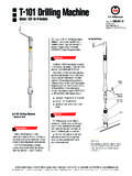
1 Spherical 3-WAY Tee with LOCK-O-RING FlangeToll Free1-888-TDWmSon (839-6766)The 4-inch through 24-inch Spherical three-way fittings are designed for use with STOPPLE Plugging Equipment to temporarily stop flow in a line. A side or bottom outlet in the fittings permits installation of a bypass around the area where flow is stopped to keep the line in service. Spherical three-way fittings are furnished with LOCK-O-RING Flanges drilled and faced to match ASME Class 150, 300 or 600 flanges. Other ASME Class ratings are available upon request. These fittings are available in 4- through 24-inch three-way fittings are compact and low-profile, with a side outlet at the same level as the main. With 4-inch through 12-inch sizes, the bottom half of the fitting can also be repositioned 180 degrees from the flange to create a bottom outlet.
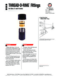
2 For 16-inch and larger sizes, the fitting must DescriptionFeaturesOptionsISO 9001 Certified Typical ApplicationsThe bottom half of the Spherical 3-WAY Tee can be turned for either a side or bottom* outlet as illustrated. The tee can also be installed AdapterSpherical 3-WAY TeeMainSide Outlet PluggerBranchBulletin No: : Indexing No: n/aSupersedes: ( ) Spherical 3-WAY Te ewith LOCK-O-RING Flange - Sizes: 4- through 24-inchbe specifically ordered as either a side or bottom outlet. Whether the outlet is to the side or on the bottom, the STOPPLE Plugging Head can stop flow in the main line while flow continues through the outlet. These fittings may be used for lateral line tie-in, temporary relocation, or permanent relocation three-way fittings are designed to a maximum operating temperature of 180 F (82 C) as per ASME , or 100 F (38 C) as per ASME All fittings are stamped with a serial number for complete material traceability.
3 Material Test Reports are available upon request. Factory welding of these fittings is 100 percent radiographically work is completed, a LOCK-O-RING Completion Plug can be installed in the neck of the fitting, permitting removal of the tapping valve. A blind flange can be installed, providing protection for the Williamson, Inc. Box 3409 Tulsa, Oklahoma 74101-3409 918-447-5100 Fax: 918-446-6327 subject to change without notice. / Dimensions not for construction unless certified. / Registered trademark of Williamson, Inc. in the United States and foreign countries / TM Trademark of Williamson, Inc. in the United States and foreign countries Dimensions and Part Numbers 4- through 24-inchASME Class 150 ASME Class 300 Maximum allowable operating pressure (in psi) per ASME at -20 to 180 F = 285 psi.
4 Maximum allowable operating pressure (in psi) per ASME at -20 to 100 F see chart below. Size Weight Design Factor Inches DN lbs Kgs .40 .50 .60 .72 Part Number 4 100 48 22 285 285 285 285 26-1863-0415-00 6 150 95 43 285 285 285 285 26-1863-0615-00 8 200 150 68 285 285 285 285 26-1863-0815-00 10 250 340 155 285 285 285 285 26-1863-1015-00 12 300 380 173 285 285 285 285 26-1863-1215-00 16 400 875 397 285 285 285 285 26-1101-0000-suff 18 450 1180 535 250 285 285 285 26-1061-0000-suff 20 500 1295 587 210 260 285 285 26-0906-0000-suff 24 600
5 2235 1013 185 230 275 285 26-0911-0000-suff Maximum allowable operating pressure (in psi) per ASME at -20 to 180 F = 740 psi. Maximum allowable operating pressure (in psi) per ASME at -20 to 100 F see chart below. Size Weight Design Factor Inches DN lbs Kgs .40 .50 .60 .72 Part Number 4 100 60 27 435 545 650 740 26-1863-0430-00 6 150 100 45 410 510 615 740 26-1863-0630-00 8 200 160 73 495 620 740 740 26-1863-0830-00 10 250 340 155 500 625 740 740 26-1863-1030-00 12 300 380 173 470 590 710 740 26-1863-1230-00 16 400 890 202 445 555 670 740 26-1103-0000-suff 18 450 1200 544 410 515 615 740 26-1063-0000-suff 20 500 1310 594 410 510 615 740 26-0907-0000-suff 24 600
6 2350 1065 425 535 640 740 , 3-WAY Tee with LOCK-O-RING FlangeASME Class 600 Maximum allowable operating pressure (in psi) per ASME at -20 to 180 F = 1480 psi. Maximum allowable operating pressure (in psi) per ASME at -20 to 100 F see chart below. Size Weight Design Factor Inches DN lbs Kgs .40 .50 .60 .72 Part Number 4 100 75 34 1000 1250 1480 1480 26-1863-0460-00 6 150 160 73 890 1115 1340 1480 26-1863-0660-00 8 200 270 123 860 1075 1290 1480 26-1863-0860-00 10 250 540 245 830 1040 1245 1480 26-1863-1060-00 12 300 750 341 930 1165 1400 1480 26-1863-1260-00 16 400 1390 630 820 1025 1230 1480 26-1104-0000-suff 18 450 1865 846 820 1025 1230 1480 26-1064-0000-suff 20 500 2390 1084 825 1030 1235 1480 26-0908-0000-suff 24 600
7 3615 1639 820 1025 1230 1480 Williamson, Inc. Box 3409 Tulsa, Oklahoma 74101-3409 918-447-5100 Fax: 918-446-6327 subject to change without notice. / Dimensions not for construction unless certified. / Registered trademark of Williamson, Inc. in the United States and foreign countries / TM Trademark of Williamson, Inc. in the United States and foreign countries