Transcription of SPLIT SET Stabilizers SS-39
1 Specifications and performanceThe SPLIT Set stabilizer is a slotted steel tube,with one end tapered for easy insertion into a drillhole. The other end has a welded ring flange tohold the bearing stabilizer is inserted into a hole slightlysmaller in diameter than the tube, using a simpledriver tool fitted to the drill. As the tube enters, itsdiameter is compressed and the slot partiallycloses. This exerts radial forces along the length ofcontact with the rock, providing the friction whichholds the rock together. The driving force of the drillactively loads the bearing plate against the Rollforms SPLIT Sets feature apatented Ring Indexing feature. This allows fordetermining the length of an installed SPLIT and plates are available standard orgalvanized, made in accordance with ASTM F 432-95 where applicable.
2 Code stampingson the tube show its size, date and place ofmanufacture, and heat lot of SS-39 SPLIT Setstabilizers are in. (39 mm) in up to 96 in.(2438 mm) are packaged 6per pack and 300 per Stabilizers are three-packed 150 per see Utility Hangers on page bearing plateSplit Set domed bearing plates uniquely combinehigh strength with light weight, and are integralparts of the SPLIT Set system. InternationalSS-39 domed plateStandardGalvanizedDimensionsWeightC omm. No. WeightComm. (mm)Lb. (kg)Lb. (kg)6 x 6 x (150 x 150 x 4) ( ) ( ) 90321274 Rollforms plates meet ASTM F 432 standardswhere applicable, providing a load capacity of 10tons ( metric tons) with minimal tubeStandardGalvanizedLengthWeightComm (mm)Lb.
3 (kg)Lb.(kg)30(762) ( ) ( )9032245436(914) ( ) ( )9032142342(1067) ( ) ( )9032246248(1219) ( ) ( )9032122560(1524) ( ) ( )9032123366(1676) ( ) ( )9032208272(1829) ( ) ( )9032124184(2134) ( ) ( )9032144996(2438) ( ) ( )90321258108(2743) ( ) ( )90322421120(3048) ( ) ( )90322439 SPLIT SET Stabilizers SS-39 The SS-39 tube has a nominaloutside diameter of inches (39mm). The length chosen should bethe same as with other types ofrock bolts, and installed with thesame stabilizer is installed with thesame drill used to make the Set Stabilizers are commonlyinstalled with jacklegs, stopers,jumbos and automatic boltingmachines. Almost any hydraulicdrill, or any percussive air drill witha bore of 2-5/8 inches (66 mm) and operating at 90psig (6 bar), will have sufficient driver toolsA simple driver tool adapts the drill for easystabilizer insertion.
4 One end fits the tube; the other fits the drill chuck or drill genuine SPLIT Set driver tools are made ofhigh-strength heat-treated alloy steel, designed forlong life, and precision-made for the proper jackleg or stoper insertion, a long-nose orshort-nose driver tool may be used. The short-nosetool is also used for driving an SS-39 SPLIT Set utilityhanger inside an installed SS-39 SPLIT drivers are available to fit drillsteel for jumbos and bolters, and for long reachwith jacklegs and rope-threaded driverInstalling the SS-39 stabilizerTypical long-nose and short-nose driversSS-39 utility hangersSplit Set utility hangers are available in 18 and 24-inch (46 and 61-cm) tube lengths tosupport light loads such as cables, vent tubing,and pipes.
5 Also, utility hangers can be driven insideinstalled SPLIT Set Stabilizers , by aligning the hanger slot with that of the stabilizer. This permits easier installation of mesh, after the ground is secured by the utility hangersLengthWeightCommIn.(mm)Lb. (kg) (457) ( ) 9032063124(610) ( ) 90321506 Galvanized18(457) ( ) 9032143124(610) ( ) 90321654SS-39 driversSteel sizeWeightComm. (mm)Lb. (kg)1(25) ( )903206071-1/4(32) ( )903200291-1/2(28) ( )90320615SS-39 driversShank sizeWeightComm. (mm)Lb. (kg)Short-nose7/8 x 4 -1/4(22 x 108) ( )72243363 Short-nose1 x 4-1/4(25 x 108) ( )72243389 Long-nose7/8 x 4-1/4(22 x 108) ( )90325481 Long-nose1 x 4-1/4(25 x 108) ( )90324740 Bit selection and drillingTo select the correct drill bit diameter for meetingthe recommended initial anchorage of 3 to 6 tons,drill several holes with bit diameters ranging from1-3/8 to 1-1/2 inch (35 to 38 mm).
6 Drill each hole atleast 2 inches (5 cm) longer than the bolt each hole and record the bit size. In soft ground, a bit may drill a holelarger than its diameter. In hard abrasiveground, the hole may be the same diameteras the bit.) Drive into each hole an SS-39 SPLIT Set stabilizerfitted with a pull collar and spacer as the driving time for each stabilizer. Afterinsertion, observe the amount of slot closure insideeach determine anchorage, perform a pull test(page 4). Align the pull tester with the stabilizer,and pressurize it until the stabilizer slips in the to be sure that it is actually the stabilizerthat has slipped. (When building up the pull load onthe stabilizer, various adjustments may occur suchas realignment of the tester housing, bearing platesettling, or localized rock crushing.
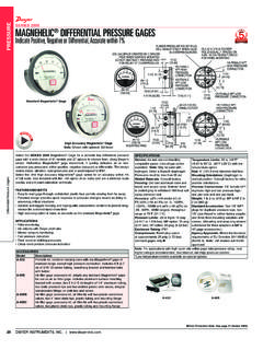
7 These must notbe mistaken for tube slippage.)Once the bolt has slipped in the hole,pressurize the tester pump until the bolt slipsagain. The same pull load should causesubsequent test dataAfter the above pull tests arecompleted, draw two graphs:(a) Anchorage versus bitdiameter.(b) Anchorage versus the first graph to determine thecorrect bit size for your particular groundcondition. As the bit wears, the hole willbecome smaller and friction will increase until the bit is replaced or the drill can t drive the bolt the second graph to establish correct drivingtime required for this ground and bolt length. With a given bit, drill, bolt length, rock characteristic andconstant pressure, insertion time will be proportionalto initial s important to establish this data for use in later spot checks, to assure that proper installationtechniques are still being mm(11/2 in.
8 37 mm36 mm35 mm(13/8 in.)Anchorage, tons876543210 Decreasing bit diameter(a) Anchorage versus bit diameterRecommendedinitial anchorage(3-6 tons)Bit range for this installationAnchorage, tons876543210 Driving time, 5 10 15 20 25 (b) Anchorage versus driving timeRecommendedinitial anchorage(3-6 tons)Expecteddrive timeSS-39 installation and pull testingSS-39 WeightComm. collarlb.(kg)andspacer ( )90320854 Application Engineering ServiceThe SPLIT Set stabilizer is a unique rockstabilization and support system. It interacts with the rock differently from otherrock bolts. For this reason, the SPLIT Set Groupoffers a free application engineering service toassist you in the selection of the proper SPLIT Setconfiguration for your needs.
9 We will also assist in determining the best way to use your existingequipment for the job, the best drilling procedure,and appropriate tools and accessories for yourequipment and space urge you to take advantage of this sales representative will be pleased to makethe pull test equipmentThe pull tester consists of two assemblies: thehydraulic portion which includes the cylinder, gage,pump, hose and adapter; and the mechanicalportion which includes the claw, housing, U-shaped bushing, spindle and the bushing removed, the clawcan be slid over the pull collar whichhas been installed with thestabilizer. When the housing andcylinder are raised, thebushing can be insertedbetween the nut and thecylinder.
10 The nut is thentightened to take up pump is then actuated toraise cylinder pressure, pulling thestabilizer slightly out of the hole throughthe bearing gage reading at slipindicates the holding force. Thedevice can be used for slip loadsup to 12 US tons ( metric tons). SS-39 pull testerDescriptionWeight Comm. (kg)Pull tester assembly ( )72233398 Mechanical ( )90321282 Hydraulic ( ) ( ) ( ) ( )90320169 Hydraulic ( )90320185 Gage ( ) ( ) ( ) ( ) ( )72233414 Hex ( )95084778 Nothing contained in this brochure is intended to extend any warranty or representation, expressed or implied, regarding the products described herein. Any such warranties or other terms and conditions of sale of products shall be in accordance with International Rollforms standard terms and conditions of sale for such products, which are available upon request.