Transcription of SPROG 3 DCC Decoder Programmer User Guide Supplement
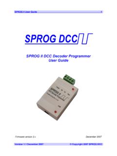
1 SPROG 3 user Guide Supplement 1 Version January 2012 Copyright 2012 SPROG DCC SPROG 3 dcc decoder programmer user guide supplement SPROG 3 user Guide Supplement 2 Version January 2012 Copyright 2012 SPROG DCC Introduction .. 3 Requirements .. 3 Features .. 3 Specification/Operating Conditions .. 4 Installation .. 5 Install SPROG 3 USB 5 The SPROG Console .. 6 Current Limit .. 6 Updates to the SPROG 3 Firmware .. 7 Firmware Update Using the Bootloader .. 7 SPROG 3 user guide supplement 3 Version January 2012 Copyright 2012 SPROG DCC Introduction SPROG 3 is a DCC Decoder Programmer and command station interface for connection to the USB port of a personal computer or similar device.
2 SPROG 3 is supported by the free JMRI software ( ) and also free. SPROG 3 is also capable of operating a medium size layout, supplying up to Amps. An even larger layout can be driven by using an external booster. Read this document in conjunction with the SPROG IIv3 user Guide available on the CD-ROM and also on the SPROG DCC website. This Supplement covers SPROG 3 specific information only: Hardware specification USB driver installation. Track output current limit Firmware updates (bootloader) Requirements JMRI from or the supplied CD-ROM Regulated DC Power Supply (see Table 1) Short length or small oval of track for programming and/or test running Rocrail, optional alternative to JMRI Features Booster stage supplying up to Amp to track Programs virtually all NMRA compliant DCC decoders No extra hardware required for programming sound decoders ( QSI, Soundtraxx)
3 Easy to use graphical interface with DecoderPro USB interface for easy connection to PC USB activity LED shows communication with the PC Power LED flashes when programming track power is live SPROG 3 user Guide Supplement 4 Version January 2012 Copyright 2012 SPROG DCC Specification/Operating Conditions Parameter Minimum Nominal Maximum Units DC Input supply voltage 10V Note 1 20V V Vin supply current not programming 50 mA Vin supply current programming 300 Note 2 mA Vin supply current Operating Layout Note 3 A Operating Temperature Range 25 C Output Load - programming 250 Note 2 mA Output Load Operating Layout Note 3 A Notes: 1. Minimum supply voltage depends upon the requirements of the Decoder being programmed.
4 In general it is safer to use as low a voltage as possible in case of problems with a newly installed Decoder . 2. SPROG 3 will remove track power if output current exceeds 250mA as measured 100ms after applying power. Surge current during Decoder power-up may be considerably greater than this. 3. To ensure correct operation of the SPROG 3 current limit, the power supply must be capable of sustaining greater then Amp. 4. SPROG 3 is protected against reverse polarity connection of the power supply but will not work unless the polarity is correct. Table 1 Specification/Operating Conditions SPROG 3 is protected against reverse polarity connection of the power supply, but will not work unless the polarity is correct.
5 SPROG 3 is not protected against track and power connections being interchanged. ! SPROG 3 user Guide Supplement 5 Version January 2012 Copyright 2012 SPROG DCC Installation Install SPROG 3 USB drivers Follow the instructions in the SPROG IIv3 user Guide but when prompted to browse to the driver directory on the CD-ROM browse to the sprog3\inf directory. For example, if your CD-ROM drive is D: browse to D:\USB\sprog3\inf as shown: SPROG 3 user Guide Supplement 6 Version January 2012 Copyright 2012 SPROG DCC The SPROG Console Operation of the SPROG console is as described in the SPROG II user Guide with the exception of the Current Limit setting. Current Limit Set the current limit for the SPROG 3 track output when using a SPROG 3 throttle, or when connected in Command Station mode.
6 The maximum current limit is 2499mA or Amps. SPROG 3 user Guide Supplement 7 Version January 2012 Copyright 2012 SPROG DCC Updates to the SPROG 3 Firmware Firmware Update Using the Bootloader Follow the instructions in the SPROG II user Guide , selecting SPROG 3 Firmware Update rather than SPROG II Firmware Update.