Transcription of SPU/SDOT Design Drafting Guidelines - …
1 SPU/SDOT Design Drafting Guidelines Page 1 of 6 SPU/SDOT Design Drafting Guidelines Design Drafting Checklists Prior to setting up drawing files: Download CAD support files at: Become familiar with the latest version of the CAD Manual and fill out a BIM Execution Plan. Acquire a Project Tracking Number (PTN) for file-naming purposes. sdot Projects: Contact the sdot Project Manager for the SpeedType (charge code). SPU Projects: Contact with the following information to obtain a PTN: SPU Project Manager (PM) Name Project Name Project Location SpeedType (charge code; obtain from PM) During 30% Design Development Setup project folders and drawings (see Section 3 of the CAD Manual).
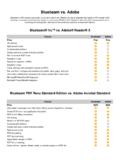
2 Set up the sheet set with Sheet Set Manager: Update project milestone field to 30% Design DRAWINGS (NOT FOR CONSTRUCTION). Fill in the Job Number - PC field with the SpeedType. Leave the Job Number - CO field blank only used for the construction SpeedType (if applicable). Fill in the Project Title field. Fill in the Total Number of Sheets field (if known). Create cover sheet. Design DrawingsSubmit 30%, 60%, 90% & 100% drawings to City of Seattle for CAD reviewsSubmit all Design change drawings to the City of SeattleAs-designed data exported to City of Seattle GISRed-LinesCompleted by contractor in the fieldAs-Built DrawingsWithin the first two weeks.
3 Submit sample as-built drawings to the City of Seattle for reviewCompleted as-built drawings shall be submitted to the City of Seattle per the contract agreementRecord DrawingsCompleted by the City of SeattleData exported to City of Seattle GISPlan set stored in the SPU Engineering Records CenterSPU/ sdot Design Drafting Guidelines Page 2 of 6 Add/modify PE stamp (color 254). Vicinity Map Location Map Sheet Index Datum Block (if applicable) Detail & Section Referencing Block Create notes sheet (see SIP web page for sample notes) with PE stamp (color 254). Setup survey control drawing with PLS stamp (color 254).
4 Set up a view drawing (XREF) that contains match lines on even stations and model space views. This drawing will be used to save-as and create all other plan/profile XREFs. XREF base map into sheets and create plan viewports based on the view drawing using Sheet Set Manager. Create Design XREFs (save-as the view drawing to create each Design drawing). Layout the Design under the direction of the project engineer. Create profiles (with match lines that match stationing on plan) if required. Add annotation based on planned viewport scale(s). Overlay Design XREFs in sheets and create viewports for profiles if required.
5 Add/modify PE stamps (color 254) on all sheets. Update description fields for each sheet in Sheet Set Manager. Review checklists in Section 4 of the CAD Manual for planning purposes. Check SPU Design Standards & Guidelines for 30% drawing requirements. Check and plot drawing set for interdepartmental plans circulation (make PDF and DWF snapshots) per Section 8 of the CAD Manual. Send the DWG files and PDF file(s) to the City per Section 10 of the CAD Manual. Send files to Project Manager and for review. During 60% Design Development Update project milestone field in Sheet Set Manager to 60% Design DRAWINGS (NOT FOR CONSTRUCTION).
6 Continue developing the drawings under the direction of the project engineer. Track and log changes during Design development. Check Design sketch for constructability throughout Drafting progress, remind designer of any noted interference or constructability concerns. Follow the Drafting & presentation Guidelines (see Section 4 of the CAD Manual). Setup detail numbers and titles using Sheet Set Manager (add cross-referencing blocks containing fields linked to Sheet Set Manager). Lock Viewports. Acquire Vault Plan Index (VPI) and serial numbers from SPU Engineering Records Center (Records Vault) and add them to the title blocks via Sheet Set Manager ( Vault Plan Number and Vault Serial Number fields).
7 If SIP is required, ensure drawings meet the 60% SIP checklist requirements. Check SPU Design Standards & Guidelines for 60% drawing requirements. SPU/SDOT Design Drafting Guidelines Page 3 of 6 Check and plot drawing set for interdepartmental plans circulation (make PDF and DWF snapshots) per Section 8 of the CAD Manual. Send the DWG files and PDF file(s) to the City per Section 10 of the CAD Manual. Send files to Project Manager and for review and asset onboarding. During 90% Design Development Update project milestone field in Sheet Set Manager to 90% Design DRAWINGS (NOT FOR CONSTRUCTION).
8 Go through the checklists in Section 4 of the CAD Manual. Prepare utility linework per Section 6 of the CAD Manual. If SIP is required, ensure drawings meet the 90% SIP checklist requirements. Check SPU Design Standards & Guidelines for 90% drawing requirements. Check and plot drawing set for interdepartmental plans circulation (make PDF and DWF snapshots) per Section 8 of the CAD Manual. Send the DWG files and PDF file(s) to the City per Section 10 of the CAD Manual. Send files to Project Manager and for review and asset onboarding. At 100% or Production of Conformed Drawing Set Update the project milestone field in Sheet Set Manager to be blank (ALT+032) or with CONFORMED DRAWING SET (MM/DD/YYYY).
9 Prepare project data for transmittal to the City. Export data from Civil 3D source drawings to LandXML. Ensure all utility linework is classified (per Section 6 of the CAD Manual) and data filled in. Transmit drawings & data (per Sections 9 and 10 of the CAD Manual) to the Project Manager and for archival and asset onboarding (applies to both SPU and sdot projects). PDFs of sheets. ZIP file of drawing package including drawing (DWG) and Sheet Set Manager (DST) files. LandXML of proposed pipe alignments/profiles (horizontal & vertical data). LandXML of proposed surfaces. Incorporate all Design changes into the CAD files as they occur and send updated CAD files to on an ongoing basis (applies to both SPU and sdot projects).
10 As-Built and Record Drawings For As-Built and Record Drawing requirements, see: Frequently Asked Questions Q. Why is it required to follow CAD standards? A. There are four main reasons: SPU/SDOT Design Drafting Guidelines Page 4 of 6 1. Readability: drawings conform to STANDARD PLAN NO 003. 2. Consistent Plotting: lineweights are controlled by the SPU/SDOT color table (CTB) file. 3. Ease of Data Transfer: drawing data is easily exported for field verification and GIS. 4. Project Efficiency: maintaining coherence, minimizing wasted effort in recreating Design , and maximizing the effectiveness of a project team.