Transcription of Stainless Steel Air Motors - Kuroda Pneumatics Ltd.
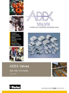
1 Stainless Steel Air Motorsaerospaceclimate control electromechanicalfiltrationfluid & gas handlinghydraulicspneumaticsprocess controlsealing & shieldingSeries P1V-S Stainless Steel Air Motors !Before carrying out service activities, make sure the air motor is vented. Before disassembling the motor , disconnect the primary air hose to ensure that the air supply is ! All technical data in the catalogue are typical values. The air quality is a major factor in the service life of the motor , see ISO CONDITIONSThe items described in this document are available for sale by Parker Hannifin Corporation, its subsidiaries or its authorized distributors. Any sale contract entered into by Parker will be governed by the provisions stated in Parker s standard terms and conditions of sale (copy available upon request).WARNINGFAILURE OR IMPROPER SELECTION OR IMPROPER USE OF THE PRODUCTS AND/OR SYSTEMS DESCRIBED HEREIN OR RELATED ITEMS CAN CAUSE DEATH, PERSONAL INJURY ANDPROPERTY document and other information from Parker Hannifin Corporation, its subsidiaries and authorized distributors provide product and/or system options for further investigation by users having technical expertise.
2 It is important that you analyze all aspects of your application and review the information concerning the product or system in the current product catalog. Due to the variety of operating conditions and applications for these products or systems, the user, through its own analysis and testing, is solely responsible for making the final selection of the products and systems and assuring that all performance, safety and warning requirements of the application are met. The products described herein, including without limitation, product features, specifications, designs, availability and pricing, are subject to change by Parker Hannifin Corporation and its subsidiaries at any time without Air Hydraulic Electric Electric Electric motor motor motor motor motor regulated regulated with feed backOverload safe ** ** * ** **Increased torque at higher loads ** ** * ** **Easy to limit torque ** ** * * **Easy to vary speed ** ** * ** **Easy to limit power ** ** * ** **Reliability ** ** ** ** **Robustness ** ** * * *Installation cost ** * ** ** **Ease of service ** ** * * *Safety in damp environments ** ** * * *Safety in explosive atmospheres ** ** * * *Safety risk with electrical installations ** ** * * *Risk of oil leak ** * ** ** **Hydraulic system required ** * ** ** **Weight ** ** * ** *Power density ** ** * * *High torque for size ** ** * * *Noise level during operation * ** ** ** **Total energy consumption * ** ** ** **Service interval * ** ** ** **Compressor capacity required * ** ** ** **Purchase price * * ** ** **Accuracy.
3 Speed * ** * ** **Regulating dynamic * * * * **Communication * * * ** ** = good, **=average, **=excellent3 Stainless Steel Air Motors PageGeneral description ..4 Principles of motor operation ..6 Torque, power and air consumption graphs ..6 Correction diagram ..7 Direction of motor rotation ..7 Speed regulation ..7 Air supply ..8 Choice of components for air supply ..8 Silencing and Sound levels ..10 Compressed air quality ..10 Choice of air motor ..1 Technical data ..14 Material specification ..14 Choice of vanes ..14 Order to the ATEX directive ..16-17 Additional safety instructions for installation in explosive atmospheres .18-19 Air MotorsP1V-S00 A series, 0 W and P1V-S008A series, 80 W .. 0P1V-S01 A/D series, 1 0 W .. P1V-S0 0A/D series, 00 W .. 4P1V-S030A/D series, 300 W .. 6P1V-S060A series, 600 W .. 8P1V-S1 0A series, 1 00 W ..30 Brake Motors , general ..3 P1V-S0 0AD series, 00 W ..33P1V-S030AD series, 300 W ..34 Installation brackets for P1V-S ..35 Dimensions for motor and BracketsMotor P1V-S00.
4 36 motor P1V-S008 ..36 motor P1V-S01 ..37 motor P1V-S0 0 ..38 motor P1V-S030 ..39 motor P1V-S060 ..40 motor P1V-S1 0 ..41 Brake motor P1V-S0 0 ..4 Brake motor P1V-S030 ..43 Drilling, milling and grinding motorsFeed movement in drilling, milling and grinding Motors ..44 Technical data: ..44 Material specification ..44 Order speeds for HSS spiral drills ..45 Drilling motor P1V-S008N ..45 Drilling motor P1V-S017N ..46 Drilling motor P1V-S017M ..47 Drilling motor P1V-S0 5N ..48 Drilling motor P1V-S0 5M ..49 Drilling motor P1V-S040M ..50 Milling motor P1V-S040N ..51 Grinding motor P1V-S009N ..5 Grinding motor P1V-S0 0N ..5 DimensionsDrilling motor P1V-S008N and P1V-S017N ..53 Drilling motor P1V-S017M and P1V-S0 5N ..54 Drilling motor P1V-S0 5M and P1V-S040M ..55 Milling motor P1V-S040N ..56 Grinding motor P1V-S009N0A000 and P1V-S0 0N0X000 ..56 Theoretical calculations ..57 Permitted shaft loadings ..60-61 Service kits for P1V-S Motors ..6 -63 Service kits for drilling, milling and grinding Motors .
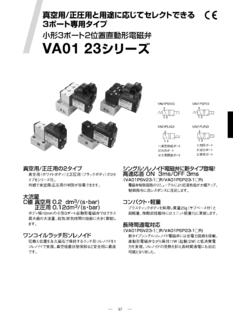
5 64 Torque, power and air consumption graphs ..654 Stainless Steel Air Motors Steel air Motors , P1V-S SeriesP1V-S is a range of air Motors with all external compo-nents made of Stainless Steel , which means that they can be used in food grade applications, and in all other applications where there is a risk of range contains seven different sizes, with powers ranging from 0 to 1 00 Watts, and speeds from 5 to 4 000 rpm. The air motor and planetary reduction gear are built into a polished Stainless Steel housing, which is sealed by a fluor rubber O-ring. The output shaft, which is made of polished Stainless Steel , is also sealed by a fluor rubber seal .Consideration for achieving a clean, hygienic design was given early on in the development of this range of air Motors . Thanks to the cylindrical shape, there are no pockets which can accumulate dirt or bacteria. Addition-ally, the two halves of the motor body are sealed with an Fluor rubber sealPlanetary gearFluor rubber O-ringLubrication-free vanes for intermittent opera-tion as air connectionOutletPolished Stainless housingHardened Stainless output shaft o-ring to prevent contamination.
6 The choice of materials reflects the fact that aggressive cleaning materials are used in food grade P1V-S series is designed to be operated in intermittent intervals under non-lubrication conditions. For this reason, no particles of lubricant escape with the exhaust air and the service costs are reduced. This means that the Motors can be used directly in food grade applications. The planetary gear, which has one or more reduction stages, is lubricated with an USDA-H1 standard grease, approved for use in food grade particularly suitable for the food Steel Air Motors Motors have much smaller installation dimensions than corresponding electric Motors can be loaded until they stall, without damage. They are designed to be able to withstand the toughest heat, vibration, impact weight of an air motor is several times less than corre-sponding electric Motors can be used in the harshest environments. Most P1V-S Motors are ATEX shape, design and non-lubricated operation allow the motor to be suitable for use in the food Motors can be stopped and started continually without simple design principle of air Motors makes them very easy to Motors are reversible as reliability of air Motors is very high, thanks to the design and the low number of moving parts.
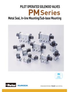
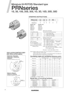
7 The choice of materials means that they can be used in damp and aggressive Steel Air Motors of motor operationThere are a number of designs of air Motors . Parker Hannifin has chosen to use the vane rotor design, because of its simple design and reliable operation. The small external dimensions of vane Motors make them suitable for all applications. The complete unit consists of a motor built together with a plan-etary reduction gear to give the required speed and torque at the output shaft. The design of a vane air motor consists of a rotor which incorporates a given number of vanes all enclosed within a cylinder. The cylinder will include three ports; an inlet pressure port, an exhaust port and a residual port. Reliable starting is ensured by the fact that the inlet air presses the vanes against the cylinder wall prior to rotation. During operation, the vanes are pressed outwards by centrifugal force. The air pressure always acts at right angles to the vane surface, which means that the available torque is determined by the surface area of the vanes and by the air pressure.
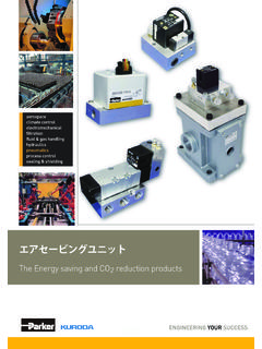
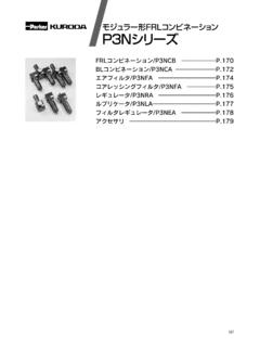
8 As each vane reached it s lowest point air is released through the exhaust port. As the rotation continues air may be trapped and compressed between vanes. This compressed air is released through the residual port. The residual port doubles as the pressure port when the motor is operated in the reverse , left Residual outlet Inlet, right1 Rotor cylinder Rotor3 Vanes4 End piece with bearingThe performance characteristics of each motor are shown in a family of curves as above, from which torque, power and air consumption can be read off as a function of speed. Power is zero when the motor is stationary and also when running at free speed (100%) with no load. Maximum power (100%) is normally developed when the motor is braked to approximately half the free speed (50%).Torque at free speed is zero, but increases as soon as a load is applied, rising linearly until the motor stalls. As the motor can stop with the vanes in various positions, it is not possible to specify an exact starting torque.
9 However, a minimum starting torque is shown in all consumption is greatest at free speed, and decreases with decreasing speed, as shown in the above , power and air consumption graphs123 OutletOutlet43124 Outlet4020608010016012014020018010010020 40608020406080 MQPQ [%], P [%]M [%]n [%]Possible working range of working range of speeds = more vane wearLower speeds with high torque = more gearbox wearThe curve is for 6 barP = power Q = air consumption M = torque n = speedPlease refer to the curve on page 65 for these pressures:3, 4, 5, 6 and 7 bar7 Stainless Steel Air Motors catalogue data and curves are specified at a supply pres-sure of 6 bar (in the inlet port). This diagram shows the effect of pressure on speed, torque, power and air off on the curve at the pressure used and then look up to the lines for power, torque, air consumption or speed. Read off the correction factor on the Y axis for each curve and multiply this by the specified catalogue data in the table or data read from the torque and power : at 4 bar supply pressure, the power is only 0,55 x power at 6 bar supply example shows how rapidly the power rating of a motor decreases as the supply pressure is reduced.
10 Therefore, it is critical to ensure that the proper pressure is supplied at the inlet port of the of motor rotationThe most common way to reduce the speed of a motor is to install a flow control in the air inlet. When the motor is used in applications where it must reverse and it is necessary to restrict the speed in both directions, flow controls with integral non-return function should be used in both directions. Restric-tion may also be applied to the main outlet which will control the speed in both directions. Inlet throttlingIf the inlet air is restricted, the air supply is restricted and the free speed of the motor falls, but there is full pressure on the vanes at low speeds. This means full torque is available from the motor at low speed, despite the low air the torque curve becomes steeper , this also means that we get a lower torque at any given speed than would be developed at full air regulationThe speed and torque can also be regulated by installing a pressure regulator in the inlet pipe.