Transcription of Standards For Aluminum Sand ENGINEERING …
1 1-12 Standards For Aluminum Sandand Permanent Mold Castings ENGINEERING SERIES (E)NOTE: The values shown herein represent normal production practice at the most economic level. Greater accuracy involving extra close work or care in production should be specified only when and where necessary since additional costs may be involved. Conversely, more liberal values should be indicated when acceptable, as these tend to keep costs to a minimum. Any variations in these values shall not be binding on the foundry unless accepted in profile is the outline of an object in a given plane. Profiles are formed by projecting a three-dimensional figure onto a plane or by taking cross sections through the figure. The elements of a profile are straight lines, arcs, and other curved profile tolerance specifies the width of a uniform zone (one half on each side of the basic profile) within which the elements of the surface must applicable, a general profile tolerance requirement may be specified in a note on the drawing.
2 The general profile tolerance should specify the datum system (usually defined by datum target points SeeAA-CS-E20, Page 1-32) from which the basic profile of the toleranced surfaces are located. (Figure 1) In determining the amount of tolerance to be specified in a general profile tolerance requirement, consideration must be given to a number of factors. The general profile tolerance should be broad enough to reflect the variations caused by expansion and contraction of the mold itself, the metal during solidification, patternmaking tolerances and vibration of the pattern during its 1 shows recommended tolerance values which should be attainable between features that are contained within the same mold half. The general profile tolerance should also allow for variance in dimensions which cross the parting line. These dimensions are affected by all of the above factors plus the hydrostatic pressure of the fluid metal which acts similar to hydraulic fluid in a cylinder trying to force the mold halves apart.
3 The amount of additional variation across the parting line, therefore, is related to the projected area of the casting at the parting line. For multiple cavity molds the projected area is the area of the mold occupied by the cavities including the area between the 2 shows recommended tolerance values which should be added to those found in TABLE 1 for dimensions crossing the parting 3 shows recommended tolerance values which should be added to those found in TABLE 1 for dimensions which include areas formed by sand or metal features which require a more stringent tolerance than the general profile tolerance should be toleranced separately in the appropriate views on the drawing. (Figure 2) E8* PROFILE TOLERANCES Page 1 of 3 Figure 1 Figure 2*Formerly AA-CS-E8-92 in previous editionsERRATA1-23 Standards For Aluminum Sandand Permanent Mold Castings ENGINEERING SERIES (E)CONCENTRICITY TOLERANCES: How to apply this standard.
4 Example below is for permanent mold Basic Tolerances Surfaces in fixed mold relationship: Cylindrical surfaces A and B are formed by the same mold section. If diameter A is 7 in. (175 mm) and diameter B is 4 in. (100 mm), diameter A will be concentric with diameter B within .031 in. (8 mm ) ( , .025 in. + (2 .003) = .031 in. [.6 mm for the first 125 mm + (2 .080)]).2. Surfaces formed by opposite mold sections: Diameters A and B are formed by opposite mold halves. If the projected area C of the casting is 10 15 in. or 150 sq. in. (1000 cm2), cylindrical surface A is 8 in. (200 mm) in diameter and cylindrical surface B is 6 in. (150 mm) in diameter, diameter A will be concentric with diameter B within .069 in. ( mm ). Projected area allowance .035 in. + basic tolerance [.025 in. + (3 .003)] = .069 in. Projected area allowance.
5 9 mm + basic tolerance [.6 mm + (3 .080)] = mm3. Surfaces formed by two moving mold members: Diameters A and B are formed by moving mold members. If diameter A is 5 in. (125 mm) and diameter B is 2 in. (50 mm), projected area of member C is 25 sq. in. (160 cm2) and projected area of mold member D is 12 sq. in. (75 cm2), diameter A will be concentric with diameter B within .075 in. ( mm ). Basic tolerance for 5 in. (125 mm) diameter ..025 area allowance for member C (25 inProjected area allowance for member D (12 in mm. 2 or 160 cm2)..030 in. mm 2 or 75 cm2)..020 in. mm .075 in. mmE12* CONCENTRICITY Page 3 of 3*Formerly AA-CS-E12-92 in previous editionsERRATA1-28 Standards For Aluminum Sandand Permanent Mold Castings ENGINEERING SERIES (E)NOTE: The values shown herein represent normal production practices. Fine detail may involve additional , trademarks, and identification symbols may be reproduced on the surfaces of sand castings.
6 This lettering can be added to the pattern by means of metal or plastic ribbons, spiked or glued letters, engraved inserts, by casting or stamping the information integrally to the pattern or by the use of inserted plugs that can be replaced if a change is LETTERS: This is the preferred method of casting lettering on a * LETTERING ( sand CASTING) Page 1 of 2 RAISED LETTERS IN A RECESS: A satisfactory alternative if raised letters on the cast surface are LETTERS: Depressed letters are more difficult to cast legibly and are not recommended for wood above illustration indicates the spacing required for 1/2 in. (12 mm) and 1/4 in. (6 mm) letters. The table below indicates the minimum width required for standard letters, in inches and * Width 10 dimensions in inches and millimeters.*Minimum sizes: Raised 1/8 in. (3 mm) minimum with 1/4 in. (6 mm) preferred. Depressed 3/16 in. (5 mm) minimum with 5/16 in.
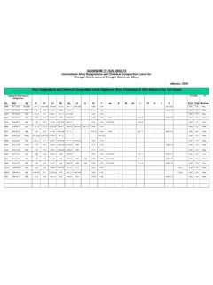
7 (8 mm) face letters will be used unless otherwise specified as this type makes a good impression in the sand and reproduces well on the casting. When lettering is to be highlighted, specify a flat face letter. Lettering should be placed on a flat surface, parallel to the parting line, with adequate space allowed (see below) and should not run into fillets or radii. Readability is reduced when placed on a curved surface or in a core.*Formerly AA-CS-E16-2000 in previous editionsERRATA2-3 Standards For Aluminum Sandand Permanent Mold Castings METALLURGICAL SERIES (M)CHEMICAL COMPOSITION LIMITS FOR COMMONLY USED sand AND PERMANENT MOLD CASTING ALLOYS a bAlloyProduct cSiliconIronCopperManganeseMagnesiumChro miumNickelZincTitaniumOthersEachTotal The alloys listed are those which have been included in Federal Specifications QQ-A-596d, Aluminum ALLOYS PERMANENT AND SEMI-PERMANENT MOLD CASTINGS, QQ-A-601E, Aluminum ALLOY sand CASTINGS, and Military Specification MIL-A-21180c, Aluminum ALLOY CASTINGS, HIGH STRENGTH.
8 Other alloys are registered with The Aluminum Association and are available. Information on these should be requested from individual foundries or ingot Except for Aluminum and Others, analysis normally is made for elements for which specific limits are shown. For purposes of determining conformance to these limits, an observed value or calculated value obtained from analysis is rounded off to the nearest unit in the last right hand place of figures used in expressing the specified limit, in accordance with the following: When the figure next beyond the last figure or place to be retained is less than 5, the figure in the last place retained should be kept unchanged. When the figure next beyond the last figure or place to be retained is greater than 5, the figure in the last place retained should be increased by 1. When the figure next beyond the last figure or place to be retained is 5 and (1) there are no figures or only zeros, beyond this 5, if the figure in the last place to be retained is odd, it should be increased by 1; if even, it should be kept unchanged.
9 (2) if the 5 next beyond the figure in the last place to be retained is followed by any figures other than zero, the figure in the last place retained should be increased by 1; whether odd or S = sand Cast P = Permanent Mold Castd If iron exceeds percent, manganese content shall not be less than one-half the iron Also contains percent Also contains percent beryllium, boron percent Also contains percent Also contains percent Also contains max. percent The sum of those Others metallic elements percent or more each, expressed to the second decimal before determining the * CHEMICAL COMPOSITION LIMITS*Formerly AA-CS-M2-84 in previous editionsiiERRATA2-4 Standards For Aluminum Sandand Permanent Mold Castings METALLURGICAL SERIES (M)M3* MECHANICAL LIMITS Page 1 of 2 MECHANICAL PROPERTY LIMITS FOR COMMONLY USED Aluminum sand CASTING ALLOYS 1 AlloyTemper 2 MINIMUM PROPERTIEST ypical Brinell Hardness 4500 kgf load10 mm ballTensile Strength% Elongation in 2 inches or 4 times diameterUltimateYield ( Offset)ksi( Mpa )ksi( Mpa ) ( 415 ) ( 345 ) ( 310 ) ( 195 ) ( 130 ) ( 85 ) ( 160 ) 65 ( 205 ) 100 ( 160 ) 55 ( 200 ) 70 ( 220 ) ( 140 ) 90 ( 165 ) ( 90 ) ( 200 ) ( 90 ) ( 220 ) ( 140 ) ( 250 ) ( 195 ) 80 ( 200 ) ( 110 ) ( 160 ) ( 90 ) ( 170 ) 65 ( 215 ) ( 140 ) ( 170 ) ( 95 ) ( 235 ) ( 145 )
10 ( 170 ) ( 125 ) 50 ( 220 ) ( 140 ) ( 240 ) 70 ( 205 ) ( 150 ) 60 ( 250 ) ( 170 ) ( 130 ) ( 160 ) ( 110 ) 45 ( 205 ) ( 140 ) ( 215 ) ( 200 ) 60 ( 170 ) ( 125 ) ( 235 ) ( 165 ) ( 115 ) ( 50 ) ( 115 ) ( 40 ) ( 115 ) ( 70 ) 35 ( 150 ) ( 60 ) ( 290 ) ( 150 ) or ( 240 ) ( 125 ) or ( 205 ) ( 115 ) ( 230 ) ( 150 ) ( 255 ) ( 205 ) or ( 220 ) ( 140 ) or ( 235 ) ( 170 ) or ( 220 ) ( 150 ) ( 290 ) ( 260 )( 185) ( 220 ) ( 250 ) ( 205 ) ( 250 ) ( 185 ) ( 290 ) ( 240 ) ( 330 ) ( 310 ) ( 110 ) ( 115 ) ( 165 ) ( 125 ) 45 751 Values represent properties obtained from separtely cast lest bars and are derived from ASTM B26/B26M, Standard Specification for Aluminum - Alloy sand Castings; Federal Specification QQ-A-601e, Aluminum Alloy sand Castings; and Military Specification MIL-A-21180c, Aluminum Alloy Castings, High Strength.