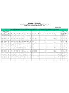
Transcription of Insulation and Related Cable Components
1 Section III Covered and Insulated Wire and Cable Chapter 8 Insulation and Related Cable Components This chapter describes in further detail the Insulation and coverings mentioned previously and also describes the jackets, shields, sheaths, and other materials used in the assembly of a Cable . An explanation of some of the dielec tric terms is in Appendix 8A. Standards are specifications for Cable Insulation and coverings are developed and set forth in the publications of ASTM, Underwriters Laboratories, Inc, (UL), and Insulated Cable Engineers Association (ICEA), and oth ers, This chapter provides summary data and the reader is advised to consult the referenced standards for further detail. Selection of insulating and other materials that sur round the conductors is based on a number of performance factors: 1. Electrical: Dielectric constant; Insulation power factor; Insulation resistance (ac and I-minute de); charg ing current; arc resistance; tracking susceptibility; ozone resistance.
2 Uniformity of potential gradient is influenced by shielding. Requirements in this category depend con siderably on voltage . 2. Mechanical: Toughness and flexibility; tensile, com pressive, and impact strengths; resistance to abrasion, crushing, and moisture; brittleness. 3. Thermal: Softening or flow temperature; expansion and contraction; compatibility with ambient, operating, emergency overload, and short-circuit conductor temperatures. 4. Chemical: Stability of materials on exposure to oils, Bame, ozone, suulight, acids, and alkalies; moisture absorption. 5. Code Requirements: Installation of Cable in accor dance with NEe and under the jurisdiction of separate electrical inspection authorities usually requires Cable labeled by Underwriters Laboratories (UL). Typical 3-Conductor Cable Assemblies The arrangement of layers of insulating and other ma~ terials around the bare conductors depends on voltage and the service application of the Cable ; that is, a Cable for aerial or in-condult installation may have a diflerent ar rangement of shields, jackets, and sheaths than one for underground burial.
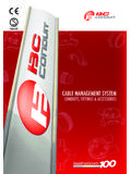
3 A different arrangement also is re quired in a Cable for series lighting circuits. Subject to such differences, and others depending on application con ditions, the following represents a customary sequence of component layers if the Insulation is of thermosetting or thermoplastic materials: Low- voltage Non-Shielded Shielded OVer S()()() V 6O()-2()()() V 2001 5()()() V (01' as low as 3001 V if required) 1. Conductor I. Conductor 1. Conductor 2. Phase.;:oded 2. Strand shielding 2. Strand shielding Insulation 3. Assembly tape 3. Phase-coded 3, Insulation and fillers Insulation 4. Jacket. sheath, 4, Assembly tape 4. Insulation shield~ or armor and fillers ing-phase identification 5, Jacket. sheath, 5, MetaUic Insulation or armor shielding 6. Assembly tape and fillers 7, Jacket, sheath. or arR' The directional control of static lines of force brought about by suitable strand and Insulation shielding is de picted in Fig. 8-1. Although details of Cable construction and materials are supplied later in this chapter, the following briefly de scribes some of the items mentioned in the above tabula tion of Cable Components .
4 The strand and Insulation shielding is normally an ex truded layer of semi-conducting material. Phase identij'lCtIti01l on non-shielded 600-5000 V cables is accomplished by a number of means, including color coding and printing on the surface of the Insulation . For shielded Cable , 5 k V and above, the Insulation is covered with an extruded semi-conducting layer. Metallic shielding is normally composed of pure zinc or copper tape, metallic braid or metal wire shields. See page 8 10. 8 1 covered and insulated wire and Cable Fig. 8-1. Diagrams that show direction ofpotential "lines of force" that extend radially from conductors within a grounded sheath: A. Cable has neither strand nor insula tion shielding; B. Cable has both strand and Insulation shielding, assuming the latter is grounded. The diagrams show the condition at the instant when voltage is zero in one of the conductors ofa three-phase circuil. Conductors for Insulated Cables As described in Chapter 7, combination strandings are more likely to be used for insulated cables than in bare conductors.
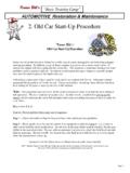
5 Thus, for the large sizes extra flexibility is ob tained by rope-concentric stranding. In this arrangement the individual uninsulated conductor is a concentric stranded group in itself, and six of these groups around one will constitute an overall body of seven groups of seven strands each. Additional layers are added in the same concentric manner. Similarly, if the individual con ductor is a bunch stranded group of small wires (the wires placed without regard to any geometric arrangement) the conductor is said to have rope-bunch stranding. The compacting of stranded conductors, made by com pressing the strands together to decrease voids, is increas ing in use because it provides the flexibility of a stranded conductor and the conductors approach the diameter of a s"lid conductor. Some of these designs in round or sector form are shown by Fig. 8-2. The Cable with a COre of fibrous material (item d) Or the segmental Cable (item e) provide reduced skin effect as compared with one of equal resistance of conventional construction.
6 The item d and item e cables, however, are little used commercially, except under special conditions. Coverings for Uninsulated Conductors The distinction between insulated conductors and unin sulated covered conductors was mentioned in Chapter 7, where it was stated that braided weather-resistant cover ings, used for decades have been superseded for power and lighting cables by thin extruded coverings of plastic-type materials, characteristics of which are covered in Table 8-1. Insulating Materials and Performance By far the most used materials for insulating aluminum conductors are those of the extruded dielectric type, the principal component being one of several materials such as ethylene-propylene rubber, cross-linked polyethylene, high molecular weight polyethylene and polyvinyl chloride. Related to these, but of less insulating quality, and hence used mostly for jackets to protect the Insulation from en vironmental conditions, are neoprene and special polyvinyl-chloride and polyethylene compounds.
7 A brief description of these materials appears later in this chapter. (0) (b) Ie) (d) (e) Fig. 8-2. Various methods ofcable strandingfor reducing (e) Compact 120-deg sector for 3-conductor Cable diameter and minimizing skin effect. (dj Hollow or fibrous core for reducing skin effect (a) Compact round (e) Segmental single conductor for reducing skin effect (b) Non-compact 120-deg sector for 3-conductor Cable (Thin Insulation is provided between segmentsj 8 2 Insulation and Related Cable Components TABLE 8-1 Some Typical Comparison Data on Extruded Materials for Non- voltage -Rated Covered Conductors Extruded Specific Grav ity Polyethylene Black Covering Cross-Linked Polyethylene Covering Tens!!e Strength, psi Elongation %, Min. Heat Distortion Brittle Temp. Cold Bend 1400 300 min. 2600 300 ",in. 121'C _80 C -55'C Abrasion Resistance Ice Forming Tendency Water Absorption, % increase Good Very low max, Good low Power Factor, 60 Hz 20 C, % Dielectric Constant, 25Q C InsuL ResistIvity, 25 C, ohm-em Breakdown strength, volts (#6 soLI max.))
8 {immersed} (immersed) 1017 (immersed) 24000 (immersedl (immersed} (immersed) 1016 (immersed) 22000 (immersed) Resistance to: Age Crack ing Sunlight Ozone Acid, Alkalies Alcohol Gasoline Oil Salt Solut'on Excellent Good Unaffected Excellent Excerlent Excellent Fair~swells slowly Poor-softens slowly Excellent Excellent Excellent Unaffected Excellent Excellent Excellent Good Good (20 C) Excellent Test MethOds are from ASTM, ANSI and UL The listed values for extruded coverings apply to the grades of mater:,,! used for' coverings. See Tables 8~2, 8-3 and 8-4 for grades of similar materials used for Insulation . 8 3 covered and insulated wire and Cable These materials are classified broadly as thermoplastic or thermosetting. Thermoplastic compounds (polyvinyl chloride and polyethylenes -not cross-linked) soften upon exposure to heat. Rubber compounds (natural and synthetic) are thermosetting; that is, upon exposure to heat under suitable conditions a chemical reaction occurs and ihe compound becomes vulcanized into a tough.))
9 Elastic condition. Alihough polyethylene is classed as a thermo plastic, it may be converted to a compound by bringing about a cross-linking of Components after the material in its thermoplastic state has been extruded around the conductor. Thus. whereas polyethylene in its typical thermoplastic form has melted at approximately 105"C. in its cross-linked form it retains about 90% of its unaged property even at 121 C. The other thermosetting rubber-like compounds if properly compounded also show high retention of initial hardness at high operating tem peratures. However, comparisons of surface hardness at various temperatures may be misleading because the hard ness usually can be controlled by additives, and too hard a surface may be undesirable.. The permissible temperature at which an insulated con ductor can operate for the expected life of ihe Cable with out impairment of Insulation Quality determines the am pacity (current-carrying capacity) of the conductor.
10 The higher the operating temperature the greater the ampacity. High operating temperatures imply high losses in the Cable and despite the ability of an Insulation to withstand certain temperature levels without losing its insulating properties, care must be exercised to determine economic conductor sizes to balance first cost and operating costs during the life of the installation. The performance of thermosetting and thermoplastic insulations for power cables has improved remarkably in recent years, both as to permissible operating temperature and oiher electrical constants, but also as to increase of useful life. Early insulations were oxygen-sensitive; that is. ihey would age from exposure to oxygen in air. In com parison, modem insulations are compounded from ma terials ihat essentially are insensitive to oxygen. The early insulations for high- voltage cables also were required to pass an ozone test at concentration for three hours. Wiih the advent of modem insulations this concentration was doubled ( ).