Transcription of Starbox - iLight
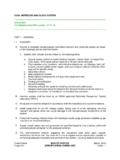
1 Starbox Installation guide Introduction Welcome Dimensions The Starbox is a wiring centre that allows iCAN. networks to be wired in a star topology (as an alternative to the standard daisy-chain topology). The Starbox is a passive device, which does not process iCAN messages nor does it appear in any of the iLight software tools used for network configuration or monitoring. The Starbox connects to seven iCAN networks. Messages input from an iCAN network, is sent to the other six iCAN networks. There is one Master and six Secondary iCAN networks. The only difference between them is that the Master must be connected as it provides power to the Starbox microprocessor. Specification Weight Packed: kg ( lbs.)
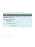
2 General Unpacked: kg ( lbs.). A. The unit requires 240 VAC 50/60Hz, 1A single phase supply B. Ambient temperature range 0 C to 40 C (32 F to 104 F). C. Humidity 5% to 95% Non-condensing D. Reprogrammable FLASH memory E. Seven iCAN networks F. Internal +12 VDC, 2A power supply G. Alarm input Product Overview 1 5. 2. 6. 3. 4 7. 1. Six Secondary network connectors each with a 4. Master network connectors (2) with a green green (power) and yellow (network activity) LED (power) and yellow (network activity) LED. 2. Starbox reset button 5. Mains Supply Terminal Block 3. Reprogramming Connector 6. Alarm input with red status LED. 7. Internal Power Supply P1. Safety ! WARNING HAZARDOUS VOLTAGES.
3 DISCONNECT FROM SUPPLY. BEFORE REMOVING COVERS. NO USER SERVICEABLE PARTS INSIDE. SERVICE BY QUALIFIED PERSONNEL ONLY. Please read this first By following the steps listed below and elsewhere within this guide , you can ensure safe installation and operation of this unit. The installation must comply with the appropriate electrical codes and regulations in force in your area. Ensure that all wiring used conforms fully to local specifications and is sufficiently rated for the installation. All new wiring must be fully verified before applying power. Ensure that high voltage and low voltage wiring remains separate. Mounting Location and spacing Mounting Holes The Starbox should be installed in a dry ventilated The unit is provided with four ( ) diameter location, where ambient conditions are maintained fixing holes for wall mounting.
4 The mounting holes can within the requirements of the unit. be accessed by undoing the four screws on the front The unit has ventilation slots on the sides to allow cover and removing it. convection cooling and under no circumstances should these be blocked. ( "). Allow 50mm (2 ) above and below the unit if trunking Mounting Holes 4-Off. with a depth greater than 50mm (2 ) is used. Ambient atmosphere requirements Temperature: 0 C to +40 C (32 F to 104 F). Humidity: 5% to 95% Non-condensing 180mm ( ). 175mm ( ). P2. Supply Wiring Connecting the Supply This unit requires a 100-240V (50-60 Hz) single phase There is no electrical isolation between iCAN. supply (live and neutral) with A capability.
5 Networks. A screwless terminal block is used to connect the mains The shield on each connector is connected to input to the internal power supply chassis ground via a 470K ohm resistor. Master iCAN Network The Master network must be used because the Starbox is powered by the 12V of the Master network. The green LED (LD1) indicates that the Master network and the Starbox is powered. As shipped from the factory, the Master network is powered by the internal power supply. Two 5 way connector blocks (CON1 and CON2) are provided for the connection of the iCAN network cable to the Master terminals. The Master iCAN network is also connected to an RJ12. (CON9) socket in parallel with CON1 and CON2.
6 The yellow LED (ACT) next to the master network connectors indicates Master iCAN network activity. Wire Gauge for Supply Terminals The live, neutral, and earth mains input are pushed into the terminals on the input side of the connector. Each of these wires can only be released by depressing the corresponding tab. Mains input cable size for live, neutral, and earth is from to Secondary iCAN Network One 5 way connector is provided for each of the six Neutral Secondary iCAN Networks (1-6, CON3-8 respectively). Earth When power (+12V and 0V) is connected to each of Live the Secondary iCAN networks the green LED (PWR) is turned ON. The yellow LED (ACT) indicates network activity on that Secondary iCAN network.
7 Each of the secondary green power LEDs must be Control Wiring connected to +12V and 0V. This can be achieved by the following options: Connect them to the master connector via wire jumpers iCAN Network Connect them to an external power supply. Connect them to an external iCANet device. All iCAN Messages received by the Starbox from any network are output to the other six iCAN. networks. P3. Alarm Input Connector CON11 (AL and 0V) provide an Alarm in- put to the Starbox . The Starbox outputs an Alarm On message to all connected iCAN networks when AL is shorted to OV. The Starbox outputs an Alarm Off message to all connected iCAN networks when the short between AL and 0V is cleared.
8 ICAN Network Wiring The following cable strategies may be used for wiring the iCAN network. It is not recommended to mix cable types in a single installation. Use Belden cable to maximise network runs up to 1000m without a bridge/repeater. Cable type: Belden 1502R or 1502P Operation Maximum cable length: 1000m (3275 ft.). Devices per segment: 100 (without bridge or repeater) Commissioning Use CAT5 FTP for economy and wide availability, but The Starbox must be energized from the mains for it to there are tighter limitations on the network run without a operate. bridge/repeater. The Master green LED indicates that the unit is powered Cable type: CAT 5 FTP correctly. Maximum cable length: 305m (1000 ft.)
9 A red flashing LED indicates that the unit is operating normally. Devices per segment: 100 (without bridge or repeater). When the red LED is ON, it indicates that there Alarm inputs are close together. Network Termination Intermittent flashing yellow LEDs indicate that iCAN. iCAN devices are daisy-chained' on the network. messages have been output on the corresponding Spurs from the network are not permitted and will network. result in communication problems. Devices on an The iCANet cables carry low voltage signals and mis- iCAN network can be wired in any order. Termination connection of these cables could result in damage to is required at both ends of the network. the Starbox and devices connected on the network.
10 Verify iCAN Networks Connect an iCANet control panel, whose buttons have been programmed with iCAN messages, to the master network and terminate appropriately. Connect a PC node to secondary 1 network and run The Starbox is provided with a termination resistor fitted iCANsoft monitor. to each iCAN network. For each iCAN network that Press a control panel button and check that the message terminates in the Starbox , keep the 120 ohm resistor sent by the control panel is received by iCANsoft monitor. connected across CAN-H and CAN-L. For each iCAN If the message is not received, check the cabling and network that does not terminate in the Starbox , remove termination resistors. the 120 ohm resistor from that connector and store it in Repeat the above process for all secondary networks.