Transcription of Steam Control and Condensate Drainage for Heat Exchangers
1 Steam Control andCondensate Drainage forHeat ExchangersBulletin FHD-206 GeneralHeat transfer units that use Steam to pro-duce hot water are known as indirectheaters. They are often shell and tubetype heat Exchangers and are generallyreferred to as converters, hot water gen-erators,and instantaneous heaters. TheASME Code for Unfired Pressure Vesselsis the nationally recognized authority pre-scribing their construction for given tem-peratures and pressures. The term usedvaries with the heating medium and themanner of application. When these heatersuse Steam as the heat source they areusually called Steam to water Steam heated converters, the water to be heated circulates through the tubesand Steam circulates in the shell sur-rounding the outside of the tubes.
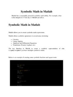
2 Thisresults in Condensate draining to the bottom of the heat exchanger shell as the Steam gives up its latent to Water Heat ExchangersThe operation of the shell and tube heatexchanger is as follows. Steam enters theheat exchanger shell through the topvapor opening and surrounds the outsideof the tubes. As energy is transferredthrough the tubes it heats the water insidethe tubes. The heat transfer condensessteam inside the shell forming condensatethat drops to the bottom of the heatexchanger shell. The Condensate flowsthrough the bottom Condensate outlet andinto a Steam trap. The Steam pressure in the heat exchangershell has a direct correlation to the tem-perature of the Condensate formed in theshell.
3 The properties of saturated steamare such that the Steam temperature varieswith Steam pressure (See Table 1 on nextpage). When the latent heat of vaporiza-tion is removed, the resulting condensatewill be close to the saturation tempera-ture. Depending on the system load,slight sub-cooling may occur from the bottom of the heat exchanger and theinlet piping to the Steam heat exchanger should be selected tooperate at the minimum possible steampressure. This allows the lowest possiblecondensate temperature to discharge fromthe Steam trap and reduces the amount offlash Steam in the return system. When heating fluids up to 200 F, the heatexchanger should be selected based on2 psig Steam pressure in the shell for themost efficient system operation.
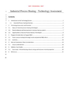
4 This may require a slightly larger heatexchanger than one operating at higherpressure, however it will result in asmaller less expensive low pressuresteam trap and a smaller Steam regulatingvalve. The low pressure selection will alsolimit the maximum temperature that canoccur inside the tubes, should the temper-ature controller fail in an open : When heating fluids up to 200 F, select heat exchanger with 2 psi Steam pressure in shell for best 415CY-STRAINERSU 84-2 HEAT EXCHANGER with OPTIONAL K HEADGT610-IPELECTRO-PNEUMATICTRANSDUCERA IR-PRVMODEL 62 VACUUM BREAKERSERIES 2000 PRESSURE TEMPERATUREREGULATORSERIES 415CY-STRAINERMODEL AP-1 AAIR PILOTSERIES CFLOAT AND THERMOSTATICSTEAM TRAPCB Condensate UNITSERIES 1 INLINE FLOATAND THERMOSTATICSTEAM TRAPSERIES 415CY-STRAINERSTEAMSUPPLYIt is standard practice to add a fouling factor in the heat exchanger fouling factor adds additional tubesurface area to assure adequate heatingafter normal scale and corrosion
5 Depositson the tube surfaces. A standard .0005fouling factor will add 20 to 25% addi-tional tube surface area. When the heatexchanger is new and the tubes are cleanand shiny, the heat exchanger will operateat lower than design pressure even at fullsystem load. For example, a new heatexchanger designed for 15 psi Steam toheat water to 160 degrees will generallyheat the full system load with 0 psi steamin the heat exchanger 1 Properties of Saturated SteamHeat Exchanger SelectionThe heat exchanger should be selectedfor operation at the minimum pressure toprovide the most efficient operation. Theproperties of saturated Steam tables showa larger amount of the latent heat is avail-able at low pressure.
6 Less energy remainsin the Condensate reducing the flashsteam losses. A reasonable guide wouldbe to select a Steam pressure that has asaturation temperature approximately30 F higher than the required outlet tem-perature of the fluid being heated in thetubes. For fluid temperatures up to 200 F,2 psig Steam is a high Steam pressure source isused, the pressure should be reduced byinstalling a Steam pressure regulatingvalve or by using a combination temper-ature pressure selecting the heat exchanger, thenext step should be planning the installa-tion. The heat exchanger should bemounted high enough to allow gravitydrainage of the Condensate from thesteam trap into a vented gravity returnline.
7 If a gravity return line is not avail-able, a Condensate pump should beinstalled. The heat exchanger should be mounted with a pitch toward the Condensate outlet. A minimum 1/2inchpitch per 10 foot length should be provided. The heat exchanger shouldalso be located such that removal of the tube bundle is possible. Steam TrapsThe Steam trap must be capable of com-pletely draining the Condensate from theheat exchanger shell under all operatingconditions. On a heat exchanger using amodulating temperature regulator to heatfluids under 212 F, the Steam pressure inthe shell can be 0 psig. To assure conden-sate Drainage , the Steam trap must bemounted below the heat exchanger outlettapping and it must drain by gravity intoa vented Condensate return unit.
8 Whenpossible, the trap should be located 15inches below the heat exchanger 15 inches static head to the trap inletwill provide 1/2psig static inlet pressure tothe trap when the shell Steam pressure isat 0 psig. The trap should be sized based on this 1/2psig differential pressure. A safetyfactor of times the calculated fullload capacity should be used to handleunusual start up loads. A float and thermostatic trap is normally the bestselection for a heat exchanger. The thermostatic element quickly vents theair from the heat exchanger shell. Themodulating float element provides continuous Condensate Drainage equal tothe system condensing rate.
9 Failure to provide complete condensatedrainage will lead to poor temperaturecontrol and possible water hammer. Anylift in the Condensate return piping afterthe trap discharge requires a positivepressure to develop in the heat exchangershell to provide Condensate Drainage . Forthis to occur, Condensate must back up in the heat exchanger shell until enoughtube surface is covered by Condensate tobuild a positive Steam pressure. Whenthe positive Steam pressure develops tomove the Condensate through the steamtrap and up the vertical return line, overheating can occur on the tube side of theheat exchanger due to the positive steampressure remaining in the shell.
10 Thisresults in a wide range of outlet fluidtemperatures from the heat lift in the return line as shown aboveshould be avoided on heat exchangersusing a modulating Control valve. (Forcorrect configurations, see diagram at top of page 4.)A lift or back pressure in the Steam trap return piping can flood the heatexchanger shell and cause severe waterhammer as Steam enters the flooded resulting water hammer can damagethe Steam trap, the Steam regulatingvalve, the heat exchanger tubes and causethe gasket in the heat exchanger and trapto InstallationThe trap should be located below theheat exchanger shell to allow free flowof Condensate into the trap.

![CO2 O HFCs PFCs SF Figure [1.1] Overview of GHG Protocol ...](/cache/preview/3/d/2/1/2/3/d/4/thumb-3d2123d4267e2c91399051a67e77df13.jpg)