Transcription of Steam Turbine Components and Systems
1 THERMAL POWER PLANTS Vol. III - Steam Turbine Components and Systems - Chaplin Steam Turbine Components AND Systems . Chaplin Department of Chemical Engineering, University of New Brunswick, Canada Keywords: Steam Turbines, Cylinders, Rotors, Blades, Seals, Bearings, Lubrication Contents 1. Turbine Cylinder Configuration Introduction Turbine Cylinders Turbine Rotors Turbine Blading S. TE S. 2. Turbine Seals General Principles R. AP LS. Gland Sealing Gland Steam system 3. Turbine Bearings C EO. General Requirements Bearing Lubrication Fire Resisting Fluid Acknowledgements E . Glossary H. Bibliography PL O. Biographical Sketch M SC. Summary Steam turbines consist essentially of a casing to which stationary blades are fixed on the SA NE. inside and a rotor carrying moving blades on the periphery.
2 The rotor is fitted inside the casing with the rows of moving blades penetrating between the rows of fixed blades. Thus Steam flowing through the Turbine passes alternately through fixed and moving blades with the fixed blades directing the Steam at the right angle for entry into the U. moving blades. Both casings and rotors must be constructed to minimize damaging thermal stresses and the moving blades must be fitted to the rotor securely to withstand the high centrifugal forces. Where the shaft of the rotor passes through the ends of the casing, a seal is required to prevent Steam leakage. Also within the casing, seals are required to prevent Steam from leaking around the blades rather than passing through them. Turbine seals are of the labyrinth type where there is no mechanical contact between the fixed and rotating parts.
3 Leakage is thus not really eliminated but merely controlled to minimal amounts. The shafts of the rotors are carried on bearings and are linked together and to the electrical generator. Bearings must be properly aligned to accommodate the natural gravitational bending of the shaft. Allowance must also be made for differential expansion between the rotors and the casings during thermal transients. Both must be Encyclopedia of Life Support Systems (EOLSS). THERMAL POWER PLANTS Vol. III - Steam Turbine Components and Systems - Chaplin free to expand without upsetting the alignment, while allowing the rotors to expand more quickly and to a greater degree than the casing. Lubrication is required for the bearings. Multiple pumps driven by alternative power sources assure adequate lubrication under all operational circumstances.
4 1. Turbine Cylinder Configuration Introduction As explained in an earlier article, large turbines are made up of several cylinders coupled together and driving a single generator. Typical units may have a high pressure cylinder, an intermediate pressure cylinder and two or three low pressure cylinders. These are designed to accommodate the increasing specific volume of the Steam as it expands down to sub-atmospheric pressures. S. TE S. Provision is also made for Steam quality improvement by reheating and for the R. AP LS. extraction of partially expanded Steam for feedwater heating. Steam conditions, particularly temperature, are limited by material properties while pressures are often dictated by the Steam supply system . C EO. The result is that the governing parameters for Turbine design are generally fairly standard and most manufacturers design their turbines within rather narrow limits.
5 Within these limits however there is scope for alternative blading design such as impulse or reaction and specialized mechanical solutions to accommodate high E . H. temperatures and pressures. In this article selected aspects of Turbine design will be considered. PL O. M SC. Turbine Cylinders Turbine cylinders have to withstand the pressure of the Steam and for this reason they are of robust design with thick walls. They are also subject to high Steam temperatures SA NE. which, for thick walled Components , are not desirable. Temperature gradients within rigid Components set up high stresses in the material which, when coupled with mechanical stress due to pressure, can cause failure of the material. U. Furthermore overall expansion of the Components must be accommodated.
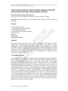
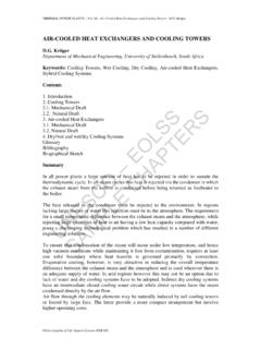
6 Also during heating and cooling the temperature gradients become particularly adverse as larger parts take longer to change their temperature than smaller parts. To withstand pressure, thick cylinder walls are required but, to minimize thermal stress, there should not be abrupt changes in thickness nor asymmetrical arrangements. This leads inevitably to smooth rounded profiles of the stress bearing Components . Also uniform heating of Components is desirable so as to avoid differential expansion and undue thermal stress. This requires sections of uniform thickness and provision for circulation of Steam within the casing as shown in Figure 1 to promote uniform temperature changes, particularly during startup of the unit. Steam access into and out of the cylinder must also be Encyclopedia of Life Support Systems (EOLSS).
7 THERMAL POWER PLANTS - Steam Turbine Components and Systems - Chaplin accommodated and this requires special nozzles and reinforcing of the casing in these areas. The incoming Steam is at a temperature higher than that generally prevailing in the cylinder necessitating appropriate arrangements to take account of thermal stress and differential expansion in these areas. In order to assemble the Turbine and to disassemble it for maintenance, the casing must be split in some way. The joint is normally horizontal so that the upper half can be removed leaving the lower half in position with the rotating parts as shown diagrammatically in Figure 1. This joint must withstand the pressure in the casing and the flanges are particularly thick and robust. These flanges may be subject to distortion during heating and cooling of the casing.
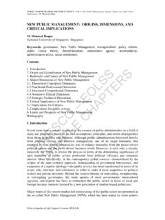
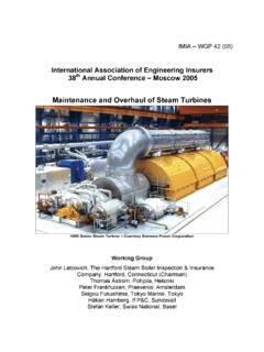
8 S. TE S. R. AP LS. C EO. E . H. PL O. Figure 1: Diagrammatic sections of Turbine cylinder M SC. Various designs make use of unique features to accommodate sometimes conflicting requirements such as thick walls for low pressure stress and thin walls for low thermal stress. Figure 2 shows a single flow high pressure Turbine of Brown Boveri design. It is SA NE. immediately apparent that there are two casings, an inner casing and an outer casing. This is now standard practice for large Steam turbines as the stress due to pressure is U. divided between the two casings resulting in lesser wall thicknesses. Also the exhaust Steam circulates in the annular space between the two casings to promote uniform heating and to minimize temperature gradients. A unique feature is the provision of shrink rings to hold the two halves of the inner casing together.
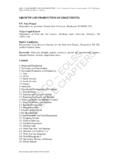
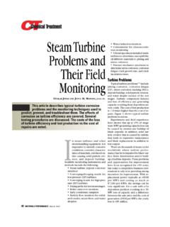
9 This avoids the need for heavy flanges and bolts and promotes uniform heating. During assembly the shrink rings are heated before fitting and grip the two halves of the casing firmly on cooling. The outer casing has conventional flanges and bolts. Once in service the inner cylinder and rotor must be removed as a unit to remove the shrink rings for maintenance of the rotor. Encyclopedia of Life Support Systems (EOLSS). THERMAL POWER PLANTS - Steam Turbine Components and Systems - Chaplin Figure 2: Single flow high pressure Turbine Another unique casing design is shown in Figure 3. This was developed by Kraftwerk Union and also overcomes the need for a very heavy flange in the high pressure S. TE S. cylinder. Instead of being split horizontally the entire outer casing of the high pressure R.
10 AP LS. Turbine is shaped like a barrel. During assembly the inner casing is slid in from the end and a large screwed plug fitted at the end. The inner casing is split vertically and bolted together with long bolts through the casing walls rather than through projecting flanges. C EO. Thermal advantages are the same as with conventional double casings. Construction of these barrel cylinders is simple but once in service the entire cylinder must be removed to withdraw the inner casing before access to the rotor can be obtained. E . H. PL O. M SC. SA NE. U. Figure 3: Single flow high pressure Turbine (courtesy of Siemens). Encyclopedia of Life Support Systems (EOLSS). THERMAL POWER PLANTS - Steam Turbine Components and Systems - Chaplin The following figures show typical Kraftwerk Union designs.