Transcription of Step by Step Wiring Procedures - GEM Remotes
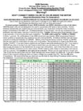
1 GEM Remotes356 Capri Blvd. Naples, FL 34113 Phone Number: Read Troubleshooting Section First! Email: , DON T CONNECT WIRES COLOR TO COLOR INSIDE THE MOTORRead All Directions Prior To Installation!Customer user instructions are printed on yellow face card inside the GEM box make sure they read them before use! Page 1 11-3-10 2010 ground wire/ N BarAmps to runBreaker Size50 Feet100 Feet200 Feet300 Feet400 FeetAmps to runBreaker Size50 Feet100 Feet200 Feet300 Feet400 Feet11 Amps141412101013 1 1 1 Recommended Wire Size for Installation of your GEM Controller-1 Phase,75C Copper Wire# of MotorsMotor HP240 Volt AC Main Feed120 Volt AC Main FeedBreakers size is our recommendation.
2 Please use motor label for proper size and code compliance. Use of other Wiring directions could result in damage to your GEM unit and/or the have 25 years of experience. We recommend that you read and use the step by step Wiring Procedures before starting the installation. It could save you time and ensure proper installation of your GEM Controller, use our new directions in lieu of all others. s If your drum switch had a corded GFI, you can use one as the main feed wire(120 VAC only).Green or bare wires must only be used as a ground. It is unsafe to use a ground as a neutral. When Wiring at 120 VAC ConnectStep by step Wiring Procedures : Tools: Philip's #2 and a flat head screwdriver, wire strippers, volt meter and wire cutters and wire nuts.
3 1. Turn off power at the circuit breaker. Overload protection is not provided inside the GEM unit. Use properly sized circuit breaker and wire size based on horsepower of motors. See wire chart below. Check that you have no voltage with a volt Remove face card screws, open slowly (be careful of the tail on the back side) if necessary remove tail by pulling on black Cut off drum (hand) switches, GEM units are not designed to be used in conjunction with hand switches. Strip main feed and motor wire inside the GEM unit. Although we recommend that you hook up your unit at 240 VAC Figure 1A (page 2), if 120vac then see drawing figure 1B (page 4). 4. Main feed black to the Lug on bottom left side of the contactor marked L1 the other main feed 120vac(white) or 240vac(red) goes to Lug L2.
4 If Wiring at 240vac with a neutral(120vac) it goes to If Wiring at 120 the GEM supplied white wire goes to L2 use the spare yellow crimp on L2 (GFI units will be pre wired do not touch transformer wires). If your unit is a GR4 or a special order 240 VAC only then you will not have white wires or a motor white Connect Motor #1 wires to Lugs on bottom right side of the contactor as labeled: Motor #1 Red(top), Motor#1 Black(middle), Motor #1 Org(bottom). Motor #2 wires if a 2 motor system attach, wires color to color inside the GEM unit using wire nuts. 6. Connect green or bare wires to Green wire on transformer. Motor white bar on the right side of the box. If a GFI unit, do not hook up the main feed white wire to the Motor white bar.
5 You must hook up your Neutral (120vac) to the GEM supplied white main feed wire. Do not tie motor wires to main feed wires. Do not attache the GEM supplied white wire to L2 if powered at 240 VAC. (Not color to color inside the motor!) If your lift has 1 motor and you where sold a Gr2 then don t use Motor 2 wires. Motor white wires to GEM motor neutral bar (Not used for 240 VAC).. Do not hook motor wire to main feed white wire!. e hite wires or a motor white Connect green or bare wires to Green wire on transformer. Green or bare wires must only be used as a ground. It is unsafe to use a ground as a neutral. When Wiring at 120 VAC Connect Motor white bar on the right side of the box.
6 If a GFI unit, do not hook up the main feed white wire to the Motor white bar. You must hook up your Neutral (120vac) to the GEM supplied white main feed wire. Do not tie motor wires to main feed wires. Do not attache the GEM supplied white wire to (Not color to color inside the motor!) If your lift has 1 motor and you where sold a Gr2 then don t use Motor 2 white wires to GEM motor neutral bar (Not used for 240 VAC).. Do not hook motor wire to main feed white wire!Fig 2 GEM BlackGEM RedGEM WhiterngGEM OaeRun Lightor an electricbrake. GEM Green Note: drum switch wire Org might be pre-wired to Motor Blk(T5)*. GEM Org needs to be attached to Pin2 or Motor Light or BrakeStandard T# or # WiresWired at 120 inside the motor!
7 !!!GEM BlackGEM RedGEM OrangeT5*(J10)T8(6)* GEM WhiteT1(P1)T3T2T4 From MotorWindings*To change motor direction, switch T5 & T8 motor Smith, Baldor, Dayton, DecoGE,Electorgear,Emerson,Leeson, Lincon, Marathon, SMC, WEG &other T# Number motor wires. To change from 120 to 240 VAC:1. Cap GEM White wire (not used).2. Attach 3 motor wires together T3,T5* and : GEM Blk to T1(P1),GEM Org to T4, GEM Red to T8(6)*. Standard T# Wires or # Wires Wired at 240 BlackGEM RedGEM OrangeT5* (J10)T8(6)*GEM WhiteT1(P1)T3T2T4 From MotorWindings * inside the motor!!!!To change motor direction, switch T5 & T8 motor Colored MotorWired at 120 inside the motor!!!!GEM BlackGEM RedGEM OrangeMotor Black* Motor Red*GEM WhiteMotor BlueMotor Orange Motor WhiteMotor YellowFrom MotorWindings*To change motor direction, switch Motor Red and Motor Black Smith, Baldor, Dayton,Electorgear, Emerson, Leeson,Lincon, Marathon and other Colored Motor wires To change from 120 to 240 VAC:1.
8 Cap GEM White wire (not used).2. Attach 3 motor wires together M Org, M Blk*and M FYI: GEM Black to Motor Blue, GEM Orange to Motor Yellow, GEM Red to Motor Red*. GEM BlackGEM RedMotor Black*Motor Red*Motor Blue Motor OrangeMotor WhiteMotor YellowFrom MotorWindings*To change motor direction, switch Motor Red and Motor Black wires inside the motor! GEM WhiteGEM OrangeStandard Colored MotorWired at 240 by step Wiring Procedures Figure 1 APage 2 11/3 Smith, Baldor, Dayton,Electorgear, Emerson, Leeson,Lincon, Marathon and otherColored Motor wires AO Smith, Baldor, Dayton, DecoGE,Electorgear,Emerson,Leeson, Lincon, Marathon SMC, WEG & other T# Motor wires SMITH 120/240 VACW ired at 120 OrangeGEM WhiteGEM RedGEM BlackL14L23 Blue JumperFrom Motor Windings Motor BlueMotor OrangeMotor WhiteMotor Red*Motor Black*Motor Yellow2 Wiring From GEM Unit*To change motor direction, switch Motor Black & Motor Red wires.
9 Note: drum switch Org might be pre-wired to Motor Black*. GEM Orange needs to be on pin 2. Also move White wires. See change from 120 to 240 VAC:1. Cap GEM White wire (not used).2. Place Motor Black on pin Move Motor Blue jumper from pin 4 to pin GEM Orange is on pin 2!!!!!!5. Move Motor White from pin 1 to SMITH Wired at OrangeGEM WhiteGEM RedGEM BlackL14L23 Blue JumperFrom Motor Windings Motor BlueMotor OrangeMotor WhiteMotor Red*Motor Black*Motor Yellow2 Wiring From GEM Unit*To change motor direction, switch Motor Black & Motor Red wires. Note: Drum switch Org might be pre-wired to Motor Black*. GEM Orange needs to be on pin 2. Also move Motor White and Motor Black wires to pin 4 and 3.
10 (P2) cap(L1)(L2)(L1)(L2)(L1)(L2)(L1)(L2)Attac h the run light to the GEM Red & GEM White for 120 VAC or 240 VAC systems that has a 120 VAC run a 120 VAC brake attach wires to GEM Orange and GEMB lack when main feed is at 120 VAC. If 240 VAC brake is used, use GEM Orange and Blk. If you have 240 VAC system and you only have a 120 VAC brake then you must use GEM White & GEM Red. (The GEM white wire will be used at 240 VAC).Hook your Main feed white wire to motor white bar. If you don t ave a Neutral (120vac) rewire transformer see page 4 line motor covers and configure motor wires as shown below. You may have to move wires inside the motor even though the drum switches worked.