Transcription of Strength of Materials - sopromat.org.ua
1 Section5 Strength of MaterialsBYJOHN SYMONDSF ellow Engineer (Retired), Oceanic Division, Westinghouse P. VIDOSICR egents Professor Emeritus of Mechanical Engineering, Georgia Institute V. HAWKINSLate Manager, Product Standards and Services, Columbus McKinnonCorporation, Tonawanda, D. DODGES upervisor (Retired), Product Quality and Inspection Technology,Manufacturing Development, Ford Motor MECHANICAL PROPERTIES OF MATERIALSby John Symonds, Expanded by StaffStress-Strain Diagrams .. 5-2 Fracture at Low Stresses.
2 5-7 Fatigue .. 5-8 Creep .. 5-10 Hardness .. 5-12 Testing of Materials .. MECHANICS OF MATERIALSby J. P. VidosicSimple Stresses and Strains .. 5-15 Combined Stresses .. 5-18 Plastic Design .. 5-19 Design Stresses .. 5-20 Beams .. 5-20 Torsion .. 5-36 Columns .. 5-38 Eccentric Loads .. 5-40 Curved Beams .. 5-41 Impact .. 5-43 Theory of Elasticity .. 5-44 Cylinders and Spheres .. 5-45 Pressure between Bodies with Curved Surfaces .. 5-47 Flat Plates .. 5-47 Theories of Failure .. 5-48 Plasticity .. 5-49 Rotating Disks.
3 5-50 Experimental Stress Analysis .. PIPELINE FLEXURE STRESSESby Harold V. HawkinsPipeline Flexure Stresses .. NONDESTRUCTIVE TESTINGby Donald D. DodgeNondestructive Testing .. 5-61 Magnetic Particle Methods .. 5-61 Penetrant Methods .. 5-61 Radiographic Methods .. 5-65 Ultrasonic Methods .. 5-66 Eddy Current Methods .. 5-66 Microwave Methods .. 5-67 Infrared Methods .. 5-67 Acoustic Signature Analysis .. 5-675-1 Copyright (C) 1999 by The McGraw-Hill Companies, Inc. All rights reserved. Use ofthis product is subject to the terms of its License Agreement.
4 Click here to MECHANICAL PROPERTIES OF MATERIALSby John Symonds, Expanded by StaffREFERENCES: Davis et al., Testing and Inspection of Engineering Materials , McGraw-Hill, Timoshenko, Strength of Materials , pt . II, Van , Engineering Materials Science, Wadsworth. Nadai, Plasticity, McGraw-Hill. Tetelman and McEvily, Fracture of Structural Materials , Wiley. Fracture Mechanics, ASTM STP-833. McClintock and Argon (eds.), Me-chanical Behavior of Materials , Addison-Wesley. Dieter, Mechanical Metal-lurgy, McGraw-Hill.
5 Creep Data, ASME. ASTM Standards, ASTM. Blaz-nynski (ed.), Plasticity and Modern Metal Forming Technology, DIAGRAMSThe Stress-Strain CurveThe engineering tensile stress-strain curveis obtained bystatic loadingof a standard specimen, that is, by applyingthe load slowly enough that all parts of the specimen are in equilibriumat any instant . The curve is usually obtained by controlling the loadingrate in the tensile machine. ASTM Standards require a loading rate notexceeding 100,000 lb/in2(70 kgf/mm2)/min. An alternate method ofobtaining the curve is to specify the strain rate as the independent vari-able, in which case the loading rate is continuously adjusted to maintainthe required strain rate.
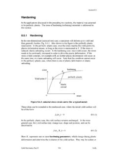
6 A strain rate of in/in/(min) is commonlyused. It is measured usually by an extensometer attached to the gagelength of the specimen. Figure shows several stress-strain stress-strain diagrams. (1) Soft brass; (2) low carbonsteel; (3) hard bronze; (4) cold rolled steel; (5) medium carbon steel, annealed; (6)medium carbon steel, heat most engineering Materials , the curve will have an initial linearelastic region (Fig. ) in which deformation is reversible and time-independent . The slope in this region isYoung s modulusE. Thepropor-tional elastic limit(PEL) is the point where the curve starts to deviatefrom a straight line.
7 Theelastic limit(frequently indistinguishable fromPEL) is the point on the curve beyond which plastic deformation ispresent after release of the load. If the stress is increased further, thestress-strain curve departs more and more from the straight line. Un-loading the specimen at pointX(Fig. ), the portionXX9is linearand is essentially parallel to the original lineOX99. The horizontal dis-tanceOX9is called thepermanent setcorresponding to the stress is the basis for the construction of the arbitraryyield the yield Strength , a straight lineXX9is drawn parallel to theinitial elastic lineOX99but displaced from it by an arbitrary value ofpermanent strain.
8 The permanent strain commonly used is percentof the original gage length. The intersection of this line with the curvedetermines the stress value called the yield Strength . In reporting theyield Strength , the amount of permanent set should be specified. Thearbitrary yield Strength is used especially for those Materials not ex-hibiting a natural yield point such as nonferrous metals; but it is notlimited to these. Plastic behavior is somewhat time-dependent , particu-larly at high temperatures. Also at high temperatures, a small amount oftime-dependent reversible strain may be detectable, indicative stress-strain tensile Strength (UTS) is the maximum load sustained bythe specimen divided by the original specimen cross-sectional area.
9 Thepercentelongation at failureis the plastic extension of the specimen atfailure expressed as (the change in original gage length3100) dividedby the original gage length. This extension is the sum of theuniformandnonuniformelongations. The uniform elongation is that which occursprior to the UTS. It has an unequivocal significance, being associatedwith uniaxial stress, whereas the nonuniform elongation which occursduring localized extension (necking) is associated with triaxial nonuniform elongation will depend on geometry, particularly theratio of specimen gage lengthL0to diameterDor square root of cross-sectional areaA.
10 ASTM Standards specify test-specimen geometry for anumber of specimen sizes. The ratioL0/ Ais maintained at for flat-and round-cross-section specimens. The original gage length shouldalways be stated in reporting elongation specimen percentreduction in area(RA) is the contraction incross-sectional area at the fracture expressed as a percentage of theoriginal area. It is obtained by measurement of the cross section of thebroken specimen at the fracture location. The RA along with the load atfracture can be used to obtain thefracture stress,that is, fracture loaddivided by cross-sectional area at the fracture.