Transcription of Defining parameters for concrete damage plasticity …
1 CHALLENGE JOURNAL OF STRUCTURAL MECHANICS 1 (3) (2015) 149 155 * Corresponding author. Tel.: +90-264-2696908 ; Fax: +90-264-2956424 ; E-mail address: (Y. S mer) Defining parameters for concrete damage plasticity model Yusuf S mer *, Muharrem Akta Department of Civil Engineering, Sakarya University, 54187 Sakarya, Turkey A B S T R A C T Behavior of reinforced concrete beam cannot be captured by elastic damage models or elastic-plastic constitutive laws only. When these two models coupled, load deflec-tion behavior of reinforced concrete can be observed through numerical modeling. Thus, using concrete damage plasticity approach in finite element modeling can lead researches for sufficient numerical results when compared to experimental tests. In order to determine the material damage model of concrete , some laboratory tests are required. This paper offers an equation for damage parameter to capture damage be-havior.
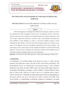
2 In addition, modeling strategies are developed by checking the model sensi-tivity against mesh density, dilation angle and fracture energy of concrete . Finite el-ement models are verified by three different experimental tests. In this study ABAQUS finite element software is employed to model reinforced concrete beam with concrete damage plasticity approach. This study shows that difference between the results from numerical models and experimental tests are in acceptable range. A R T I C L E I N F O Article history: Received 14 May 2015 Accepted 11 July 2015 Keywords: Finite element method Reinforced concrete beam Plastic damage model Failure mechanisms 1. Introduction Constitutive behavior of concrete is very difficult to capture by using elastic damage models or elastic plastic laws. In elastic damage model irreversible strains cannot be captured. It can be seen in Fig.
3 1(b) that a zero stress corresponds to a zero strain which makes damage value to be overestimated. On the other hand when elastic plastic relation is adopted the strain will be overesti-mated since the unloading curve will follow the elastic slope (Fig. 1(c)). concrete damage plasticity (CDP) model which combines these two approaches can cap-ture the constitutive behavior of experimental unloading (Fig. 1(a)) (Jason et al., 2004). Fig. 1. Elastic plastic damage law (Jason et al., 2004). In this model two main failure mechanisms are as-sumed: tensile cracking and compressive crushing of the concrete . The evolution of the yield surface is controlled by tensile and compressive equivalent plastic strains. In the following sections main assumptions about this model will be discussed in detail. In this study, develop-ing a finite element model along with required parame-ters is discussed.
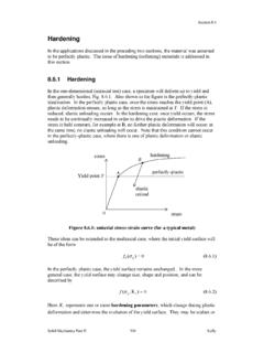
4 ABAQUS nonlinear finite element com-mercial software package is employed. All the modeling parameters are validated by experimental results. 2. Material Constitutive Behaviors Numerical models for the constituent material prop-erties are described in this section. concrete model CDP is one of the possible constitutive models to pre-dict the constitutive behavior of concrete . It describes the constitutive behavior of concrete by introducing sca-lar damage variables. Tensile and compressive response of concrete can be characterized by CDP in Fig. 2. 150 S mer and Akta / Challenge Journal of Structural Mechanics 1 (3) (2015) 149 155 Fig. 2. Behavior of concrete under axial compressive (a) and tension(b) strength (Abaqus User Manual, 2008). As shown in Fig. 2, the unloaded response of concrete specimen seems to be weakened because the elastic stiff-ness of the material appears to be damaged or degraded.
5 The degradation of the elastic stiffness on the strain sof-tening branch of the stress-strain curve is characterized by two damage variables, dt and dc, which can take values from zero to one. Zero represents the undamaged mate-rial where one represents total loss of strength (Abaqus User Manual, 2008). E0 is the initial (undamaged) elastic stiffness of the material and ~ , ~ , ~ , ~ are compressive plastic strain, tensile plastic strain, com-pressive inelastic strain and tensile inelastic strain re-spectively. The stress-strain relations under uniaxial tension and compression are taken into account in Eq. (1) and Eq. (2). = (1 ) 0 ( ~ ) , (1) = (1 ) 0 ( ~ ) . (2) Interface behavior between rebar and concrete is modeled by implementing tension stiffening in the con-crete modeling to simulate load transfer across the cracks through the rebar.
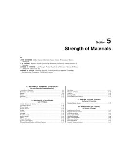
6 Tension stiffening also allows to model strain- softening behavior for cracked concrete . Thus it is necessary to define Tension stiffening in CDP model. ABAQUS allows us to specify Tension Stiffening by post failure stress-strain relation or by applying a fracture energy cracking criterion (Abaqus User Manual, 2008). There is a mesh sensitivity problem when cracking failure in not distributed evenly. This phenomenon ex-ists when there is no reinforcement in significant regions of the model. To overcome this unreasonable mesh sen-sitivity problem Hillerborg s (1976) fracture energy ap-proach can be used instead of post failure stress-strain relation (Hillerborg et al., 1976). In this approach; the amount of energy (GF) which is required to open a unit area of crack is assumed as a material property. Thus; concrete s brittle behavior is defined by stress-displace-ment response rather than a stress-strain response.
7 Spec-ifying the post failure stress versus corresponding crack-ing displacement is enough to describe this approach as shown in Fig. 3(a-b) (Abaqus User Manual, 2008). Fig. 3. Post failure stress-strain relation with fracture en-ergy approach (Abaqus User Manual, 2008). As an alternative, GF can be implemented directly as a material property. However in this case, a linear loss of strength after cracking is assumed (Fig. 3(b)). From CDP perspective, ABAQUS automatically calculates both plas-tic displacement values using the Eq. (3) and Eq. (4). = (1 ) 0 0 , (3) ~ = ~ (1 ) 0 . (4) From these equations effective tensile and compres-sive cohesion stresses ( , ) can be defined as: = (1 )= 0( ) , (5) = (1 )= 0( ~ ) . (6) The effective cohesion stresses determines the size of the yield (or failure) surface (see Fig. 4). In Abaqus the parameters required to define the yield surface consists (a) (b) (a) (b) S mer and Akta / Challenge Journal of Structural Mechanics 1 (3) (2015) 149 155 151 of four constitutive parameters .
8 The Poisson s ratio con-trols the volume changes of concrete for stresses below the critical value which is the onset of inelastic behavior. Once the critical stress value is reached concrete exhibits an increase in plastic volume under pressure (Chen, 1982). This behavior is taken into account by Defining a parameter called the angle of dilation. In CDP model is the dilation angle measured in the p-q plane at high con-fining pressure and in this study it is determined with sensitivity analysis. is an eccentricity of the plastic po-tential surface with default value of The ratio of ini-tial biaxial compressive yield stress to initial uniaxial compressive yield stress, b0/ c0, with default value of Finally Kc is the ratio of the second stress invariant on the tensile meridian to compressive meridian at ini-tial yield with default value of 2/3 (Abaqus User Manual, 2008).
9 The parameter Kc should be defined based on the full triaxial tests of concrete , moreover biaxial labora-tory test is necessary to define the value of b0/ c0. This paper does not discuss the identification procedure for parameters , b0/ c0, and Kc because tests that are going to be verified in this study do not have such information. Thus, default values are accepted in this study. Fig. 4. Biaxial yield surface in CDP Model (Abaqus User Manual, 2008). Uniaxial tension and compression stress behavior of test model Since the compression and tension stress behavior of the experimental test specimens are not reported these relations are created by using mathematical models from literature. The compressive behavior of concrete is obtained by employing Hognestad probala along with linear descending branch. However the crushing of con-crete is affected by the closed stirrups and some modifi-cations are made for concrete in compression according to CEB-FIP MC90 (Fig.)
10 5(a)) (CEB-FIB, 1993). Equation of the parabola is shown in Eq. (7) where is the com-pressive stress, fcu is ultimate compressive stress, c* is the peak compressive strain, E is the elastic modulus and fc* is the modified compressive strength. Details of this model can be found in Arduini et al., 1997. = (2 [ ]2) . (7) Fig. 5. Stress-strain behavior of concrete under uniaxial compression and tension a) Hognestad concrete com-pressive behavior b) Bilinear tensile behavior. For tensile behavior of concrete , bilinear model is adopted as plotted in Fig. 5(b) (Coronado and Lopez, 2006). Crack opening (wc) is calculated as a ratio of the total external energy supply (GF) per unit area required to create, propagate and fully break a Mode I crack in concrete . However; Mode I tensile fracture energy of concrete is defined as a function of the concrete com-pressive strength, fc*, in CEB-FIP MC90 (CEB-FIB, 1993) as shown in Eq.