Transcription of STRESS AND DEFORMATION ANALYSIS - Pearson
1 87 The Big PictureYou Are the Designer3 1 Objectives of This Chapter3 2 Philosophy of a Safe Design3 3 Representing Stresses on a STRESS Element3 4 Normal Stresses Due to Direct Axial Load3 5 DEFORMATION under Direct Axial Load3 6 Shear STRESS Due to Direct Shear Load3 7 Torsional Load Torque, Rotational Speed, and Power3 8 Shear STRESS Due to Torsional Load3 9 Torsional DEFORMATION 3 10 Torsion in Members Having Non-Circular Cross Sections 3 11 Torsion in Closed Thin-Walled Tubes 3 12 Torsion in Open Thin-Walled Tubes 3 13 Shear STRESS Due to Bending 3 14 Shear STRESS Due to Bending Special Shear STRESS Formulas 3 15 Normal STRESS Due to Bending 3 16 Beams with Concentrated Bending Moments 3 17 Flexural Center for Beam Bending 3 18 Beam Deflections 3 19 Equations for Deflected Beam Shape 3 20 Curved Beams 3 21 Superposition Principle 3 22 STRESS Concentrations 3 23 Notch Sensitivity and Strength Reduction FactorSTRESS AND DEFORMATION ANALYSISCHAPTERTHREETHE BIG PICTURED iscussion Map As a designer, you are responsible for ensuring thesafety of the components and systems you design.
2 You must apply your prior knowledge of the prin-ciples of strength of could consumer products and machines fail?Describe some product failures you have and DEFORMATION AnalysisThis chapter presents a brief review of the fundamentals of STRESS ANALYSIS . It will help you design products that do not fail, and it will prepare you for other topics later in this designer is responsible for ensuring the safety of the components and systems that he or she designs. Many factors affect safety, but one of the most critical aspects of design safety is that the level of STRESS to which a machine component is subjected must be safe under reasonably foreseeable conditions. This prin-ciple implies, of course, that nothing actually breaks. Safety may also be compromised if components are 873/14/17 3:47 PM88 PART onE Principles of Design and STRESS ANALYSIS ARE THE DEsignERYou are the designer of a utility crane that might be used in an auto-motive repair facility, in a manufacturing plant, or on a mobile unit such as a truck bed.
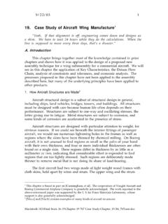
3 Its function is to raise heavy schematic layout of one possible configuration of the crane is shown in Figure 3 1. It is comprised of four primary load-carrying members, labeled 1, 2, 3, and 4. These members are connected to each other with pin-type joints at A, B, C, D, E, and F. The load is applied to the end of the horizontal boom, member 3. Anchor points for the crane are provided at joints A and B that carry the loads from the crane to a rigid structure. Note that this is a simpli-fied view of the crane showing only the primary structural compo-nents and the forces in the plane of the applied load. The crane would also need stabilizing members in the plane perpendicular to the 3 1 Schematic layout of a craneBoomLOADF3 GEDCS trutRigid baseFloorVertical supportBraceBA241(a) Pictorial view(b) Side Viewpermitted to deflect excessively, even though nothing have already studied the principles of strength of materials to learn the fundamentals of STRESS ANALYSIS .
4 Thus, at this point, you should be com-petent to analyze load-carrying members for STRESS and deflection due to direct tensile and compressive loads, direct shear, torsional shear, and , now, about consumer products and machines with which you are familiar, and try to explain how they could fail. Of course, we do not expect them to fail, because most such products are well designed. But some do fail. Can you recall any? How did they fail? What were the operating condi-tions when they failed? What was the material of the components that failed? Can you visualize and describe the kinds of loads that were placed on the components that failed? Were they subjected to bend-ing, tension , compression, shear, or torsion? Could there have been more than one type of STRESS acting at the same time?
5 Are there evidences of accidental over-loads? Should such loads have been anticipated by the designer? Could the failure be due to the manufacture of the product rather than its design?Talk about product and machine failures with your associates and your instructor. Consider parts of your car, home appliances, lawn maintenance equip-ment, or equipment where you have worked. If pos-sible, bring failed components to the meetings with your associates, and discuss the components and their of this book emphasizes developing special methods to analyze and design machine elements. These methods are all based on the fundamentals of STRESS ANALYSIS , and it is assumed that you have com-pleted a course in strength of materials. This chapter presents a brief review of the fundamentals. (See Ref-erences 2 4.)
6 883/14/17 3:47 PM CHAPTER THREE STRESS and DEFORMATION ANALYSIS 89 You will need to analyze the kinds of forces that are exerted on each of the load-carrying members before you can design them. This calls for the use of the principles of statics in which you should have already gained competence. The following discussion provides a review of some of the key principles you will need in this work as a designer proceeds as follows:1. Analyze the forces that are exerted on each load-carrying mem-ber using the principles of Identify the kinds of stresses that each member is subjected to by the applied Propose the general shape of each load-carrying member and the material from which each is to be Complete the STRESS ANALYSIS for each member to determine its final s work through steps 1 and 2 now as a review of statics.
7 You will improve your ability to do steps 3 and 4 as you perform several prac-tice problems in this chapter and in Chapters 4 and 5 by reviewing strength of materials and adding competencies that build on that AnalysisOne approach to the force ANALYSIS is outlined Consider the entire crane structure as a free-body with the applied force acting at point G and the reactions acting at sup-port points A and B. See Figure 3 2, which shows these forces and important dimensions of the crane Break the structure apart so that each member is represented as a free-body diagram, showing all forces acting at each joint. See the result in Figure 3 Analyze the magnitudes and directions of all are given here to summarize the methods used in the static ANALYSIS and to report results. You should work through the details of the ANALYSIS yourself or with colleagues to ensure that you can perform such calculations.
8 All of the forces are directly propor-tional to the applied force F. We will show the results with an assumed value of F= kN (approximately 2250 lb).Step 1: The pin joints at A and B can provide support in any direc-tion. We show the x and y components of the reactions in Figure 3 2. Then, proceed as follows:1. Sum moments about B to findRAy= F= kN2. Sum forces in the vertical direction to findRBy= F= this point, we need to recognize that the strut AC is pin- connected at each end and carries loads only at its ends. Therefore, it is a two-force member, and the direction of the total force, RA, acts along the member itself. Then RAy and RAx are the rectangular components of RA as shown in the lower left of Figure 3 2. We can then say thattan ( )=RAy/RAxand thenRAx=RAy/tan ( )= kN/tan ( )= kNFIGURE 3 2 Free-body diagram of complete crane E7501250750500CB1 GLoad, Dimensions in millimeters2500 Reaction forces at supports A and 893/14/17 3:47 PM90 PART onE Principles of Design and STRESS AnalysisThe total force, RA, can be computed from the Pythagorean theorem,RA=3 RAx2+RAy2=3( )2+( )2= kNThis force acts along the strut AC, at an angle of above the horizontal, and it is the force that tends to shear the pin in joint A.
9 The force at C on the strut AC is also kN acting upward to the right to balance RA on the two-force member as shown in Figure 3 3. Member AC is therefore in pure can now use the sum of the forces in the horizontal direc-tion on the entire structure to show that RAx=RBx= resultant of RBx and RBy is kN acting at an angle of above the horizontal, and it is the total shearing force on the pin in joint B. See the diagram in the lower right of Figure 3 2: The set of free body diagrams is shown in Figure 3 3: Now consider the free-body diagrams of all of the members in Figure 3 3. We have already discussed member 1, recog-nizing it as a two force member in tension carrying forces RA and RC equal to kN. The reaction to RC acts on the vertical member note that member 2 is also a two-force member, but it is in compression rather than tension .
10 Therefore, we know that the forces on points D and F are equal and that they act in line with member 2, with respect to the horizontal. The reactions to these forces, then, act at point D on the vertical support, member 4, and at point F on the horizontal boom, member 3. We can find the value of RF by considering the free-body diagram of member 3. You should be able to verify the following results using the methods already demonstrated. RFy= F=( )( kN)= kN RFx= F=( )( kN)= kN RF= F=( )( kN)= kN REy= F=( )( kN)= kN REx= F=( )( kN)= kN RE= F=( )( kN)= kNNow all forces on the vertical member 4 are known from earlier analyses using the principle of action-reaction at each of Stresses on Each MemberConsider again the free-body diagrams in Figure 3 3 to visualize the kinds of stresses that are created in each member.