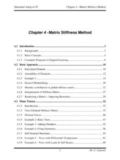
Transcription of Structural Analysis III The Moment Area Method – …
1 Structural Analysis III Dr. C. Caprani 1 Structural Analysis III The Moment Area Method Mohr s Theorems 2007/8 Dr. Colin Caprani, Chartered Engineer Structural Analysis III Dr. C. Caprani 21. introduction Purpose The Moment -area Method , developed by Mohr, is a powerful tool for finding the deflections of structures primarily subjected to bending. Its ease of finding deflections of determinate structures makes it ideal for solving indeterminate structures, using compatibility of displacement. We will examine compatibility of displacement in more detail later, but its essence is the knowledge of certain displacements.
2 For example, we know that the displacement of a simply supported beam is zero at each support. We will use this information, in association with Mohr s Theorems, to solve for related indeterminate beams. Structural Analysis III Dr. C. Caprani 32. Theory Basis We consider a length of beam AB in its undeformed and deformed state, as shown on the next page. Studying this diagram carefully, we note: 1. AB is the original unloaded length of the beam and A B is the deflected position of AB when loaded. 2. The angle subtended at the centre of the arc A OB is and is the change in curvature from A to B.
3 3. PQ is a very short length of the beam, measured as ds along the curve and dx along the x-axis. 4. d is the angle subtended at the centre of the arc ds. 5. d is the change in curvature from P to Q. 6. M is the average bending Moment over the portion dx between P and Q. 7. The distance is known as the vertical intercept and is the distance from B to the produced tangent to the curve at A which crosses under B at C. It is measured perpendicular to the undeformed neutral axis ( the x-axis) and so is vertical . Structural Analysis III Dr. C. Caprani 4 Basis of Theory Structural Analysis III Dr. C. Caprani Mohr s First Theorem (Mohr I) Development Noting that the angles are always measured in radians, we have: dsR ddsRd = = From the Euler-Bernoulli Theory of Bending, we know: 1 MREI= Hence: MddsEI = But for small deflections, the chord and arc length are similar, dsdx , giving: MddxEI = The total change in rotation between A and B is thus: BBAAMddxEI = Structural Analysis III Dr.
4 C. Caprani 6 The term MEI is the curvature and the diagram of this terms as it changes along a beam is the curvature diagram (or more simply the MEI diagram). Thus we have: BBABAAMddxEI = = This is interpreted as: []Change in slopeArea of diagramABABMEI = This is Mohr s First Theorem (Mohr I): The change in slope over any length of a member subjected to bending is equal to the area of the curvature diagram over that length. Usually the beam is prismatic and so E and I do not change over the length AB, whereas the bending Moment M will change. Thus: 1 BABAMdxEI = [][]Area ofdiagramChange in slopeABABMEI= Structural Analysis III Dr.
5 C. Caprani 7 Example 1 For the cantilever beam shown, we can find the rotation at B easily: Thus, from Mohr I, we have: []Change in slopeArea of diagram12 ABABBAMEIPLLEI = = Since the rotation at A is zero (it is a fixed support), 0A =, we have: 22 BPLEI = Structural Analysis III Dr. C. Caprani Mohr s Second Theorem (Mohr II) Development From the main diagram, we can see that: dxd = But, as we know from previous, MddxEI = Thus: MdxdxEI = And so for the portion AB, we have: First Moment of diagram about BBAABBAAM dxdxEIMdx xEIMBEI = = = This is easily interpreted as: Structural Analysis III Dr.
6 C. Caprani 9 Distance from to centroid Area of Verticalof diagramIntercept diagramBABABABMMEIEI = This is Mohr s Second Theorem (Mohr II): For an originally straight beam, subject to bending Moment , the vertical intercept between one terminal and the tangent to the curve of another terminal is the first Moment of the curvature diagram about the terminal where the intercept is measured. There are two crucial things to note from this definition: Vertical intercept is not deflection; look again at the fundamental diagram it is the distance from the deformed position of the beam to the tangent of the deformed shape of the beam at another location.
7 That is: The Moment of the curvature diagram must be taken about the point where the vertical intercept is required. That is: BAAB Structural Analysis III Dr. C. Caprani 10 Example 2 For the cantilever beam, we can find the defection at B since the produced tangent at A is horizontal, 0A =. Thus it can be used to measure deflections from: Thus, from Mohr II, we have: 1223 BAPLLLEI = And so the deflection at B is: 23 BPLEI = Structural Analysis III Dr. C. Caprani Area Properties These are well known for triangular and rectangular areas. For parabolic areas we have: Shape Area Centroid 23 Axy= 12xx= 23 Axy= 58xx= 13 Axy= 34xx= Structural Analysis III Dr.
8 C. Caprani 123. Application to Determinate Structures Basic Examples Example 3 For the following beam, find B , C , B and C given the section dimensions shown and 210 kN/mmE=. To be done in class. Structural Analysis III Dr. C. Caprani 13 Example 4 For the following simply-supported beam, we can find the rotation at A using Mohr s Second Theorem. The deflected shape diagram is used to identify relationships between vertical intercepts and rotations: The key to the solution here is that we can calculate BA using Mohr II but from the diagram we can see that we can use the formula SR = for small angles: BAAL = Therefore once we know BA using Mohr II, we can find ABAL =.
9 To calculate BA using Mohr II we need the bending Moment and curvature diagrams: Structural Analysis III Dr. C. Caprani 14 Thus, from Mohr II, we have: 3124 216 BAPLLLEIPLEI = = But, BAAL = and so we have: 216 BAALPLEI == Structural Analysis III Dr. C. Caprani Finding Deflections General Procedure To find the deflection at any location x from a support use the following relationships between rotations and vertical intercepts: Thus we: 1. Find the rotation at the support using Mohr II as before; 2. For the location x, and from the diagram we have: xBxBx = Structural Analysis III Dr.
10 C. Caprani 16 Maximum Deflection To find the maximum deflection we first need to find the location at which this occurs. We know from beam theory that: ddx = Hence, from basic calculus, the maximum deflection occurs at a rotation, 0 =: To find where the rotation is zero: 1. Calculate a rotation at some point, say support A, using Mohr II say; 2. Using Mohr I, determine at what distance from the point of known rotation (A) the change in rotation (Mohr I), Axd equals the known rotation (A ). 3. This is the point of maximum deflection since: 0 AAxAAd = = Structural Analysis III Dr. C. Caprani 17 Example 5 For the following beam of constant EI: (a) DetermineA , B and C ; (b) What is the maximum deflection and where is it located?