Transcription of Structural Design of Raft Foundation
1 Page | 1 QATAR UNIVERSITY COLLAGE OF ENGINEERING COURSE: Design OF REINFORCED CONCRETE STRUCTURES Structural Design of Raft Foundation Submitted to: Dr. Mohammed Al-ansari Prepared by: Haytham Adnan Sadeq Mohammed Saleem Taha Date of submission: 01-01-2009 Page | 2 Acknowledgment: After completing this special project in Design of raft Foundation for the course of Design of reinforced concrete structures, we are deeply indebted to the people who contributed in various ways towards its progress and completion We are grateful to Dr. Mohammed Al-Ansari for his continuous goodness and encouragement. We would also like to express our deepest for our families and friends who helped in the success of this project. Page | 3 Abstract: In this report, a full discussion and clarification of the Design of Raft Foundation in loose sand will be shown in details.
2 The columns loads calculation for this raft is also will be shown in terms of the turbidity area of the columns. Final Design and detailing will be shown at the end of this report with SAFE software Design out file attached. Page | 4 Table of Contents: Acknowledgment: .. 1 Abstract: .. 3 List of Figures: .. 5 List of Tables: .. 6 1. Introduction: .. 7 2. Objective: .. 8 3. Raft Modeling and Analysis: .. 9 Raft dimensions: .. 9 Columns loads in Raft:.. 10 Why Raft should be used: .. 13 Raft thickness: .. 14 Raft Depth check: .. 15 One way shear: .. 15 Two way shear (interior column): .. 16 SAFE Punching Shear check: .. 16 Soil Pressure Check: .. 17 SAFE Settlement Analysis: .. 20 Moments Strips SAFE results: .. 21 X direction strips .. 21 Y direction strips .. 22 4. Manual & Computer Design : .. 23 X-strip Design .
3 23 Y-strip Design : .. 25 Comparison Table: .. 27 Detailing: .. 27 5. Conclusion: .. 28 6. References: .. 29 7. Index: .. 30 Page | 5 List of Figures: Figure 1, Raft layout .. 9 Figure 2, Raft dimension and column spacing .. 10 Figure 3, Column Design .. 12 Figure 4, Diagonal tension shear area .. 14 Figure 5, C4 shear diagram .. 15 Figure 6, maximum shear in strips CSY3 .. 15 Figure 7, two way shear area .. 16 Figure 8, punching shear factors for the raft .. 16 Figure 9, resultant position due to column loads .. 17 Figure 10, columns total service loads (DL+LL) .. 18 Figure 11, corners of raft .. 19 Figure 12, settlement of Raft using SAFA software .. 20 Figure 13, X-strip moment diagram .. 21 Figure 14, Y-strip moment 22 Page | 6 List of Tables: Table 1, parmaters used in Raft Design .. 8 Table 2, Design loads .. 10 Table 3, all columns loads.
4 11 Table 4, Properties taken in Raft Design .. 13 Table 5, x-strips moments values .. 21 Table 6, y-strips moments values .. 22 Table 7, comparison between manual and computer Design .. 27 Design of Raft Foundation Page | 7 1. Introduction: This Foundation will be done for a storage 5 story building. The raft will be used for economical consideration. The justification of using raft Foundation will be discussed in columns loads section The raft Foundation is a kind of combined footing that may cover the entire area under the structure supporting several columns in one rigid body. In this project, the soil profile shows that the bearing stress is around 100 kN/m2 . The raft Foundation is usually used with this kind of soil. The columns have high axial loads. If spread footings used, the area of the footing required will be big as will be shown in column load section In this big spread footing condition, the raft Foundation could be much practical and economical.
5 In this project, the raft will be designed as flat plate, which has a uniform thickness and without any beams or pedestals. Design of Raft Foundation Page | 8 2. Objective: This report shows the Structural Design of the raft Foundation . The raft is modeled in SAFE software. All analysis and Design are based on the ACI code. Raft Foundation can be Design using several methods. In this special project the method used in the Design called the Conventional Rigid Method and all Design steps will be shown in the report. All Design parameters are shown in table 1. Parameter Notation Value Yield strength of steel Fy 400 MPa Strength of concrete fc 30 MPa Young modules of elasticity E 2000000 Dear load factor Live load factor .F Soil Unit weight soil 15 kN/m3 Allowable Bearing stress qa 100 kN/ m2 Concrete Unit weight concrete 25 kN/ m3 Table 1, parmaters used in Raft Design Design of Raft Foundation Page | 9 3.
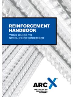
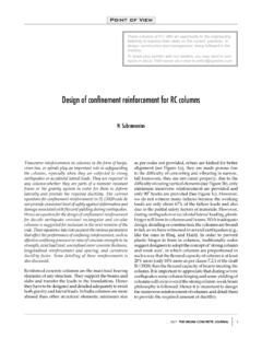
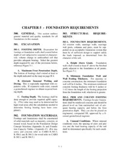
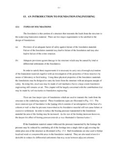
6 Raft Modeling and Analysis: Raft dimensions: Raft Foundation has been modeled in SAFE software. The raft has x side spacing of 7 meters and y-side spacing of 6 meters. One meter edge is around the edges columns. The plan of the raft is shown in figure 1. Figure 1, Raft layout The total area of the raft = 3 7 +1+1 3 6 +1+1 =23 20=460 2 Design of Raft Foundation Page | 10 Columns loads in Raft: The industrial building that this raft is designed for has 5 stories with dead and live loads which are shown in table 2. Load type Load case Load value (kN/m2) Services Dead kN/m2 Slab own weight assumed Dead (25kN/m3)( ) = 5 kN/m2 Flooring Dead 1 kN/m2 Live loads Live 7 kN/m2 Table 2, Design loads Figure 2 shows the columns notation and the yellow lines shows the turbidity areas that are covered by the columns. Figure 2, Raft dimension and column spacing Loads per square meter are calculated as: = 5+ +1 2.
7 = 5+ +1 2 5= / 2 = 7 2 5=35 / 2 Design of Raft Foundation Page | 11 Columns loads: = 2 Column type (1): Axial unfactored Dead load = kN/m2 4 m2=765 kN Axial unfactored Live load =35 kN/m2 4 m2=630 kN Total Sevice Axial load =765+630 kN=1395 kN Ultimate axial load = 765 + 630 =1926 kN Column type (2): Axial unfactored Dead load = kN/m2 4 7 m2=1190 kN Axial unfactored Live load =35 kN/m2 4 7 m2=980 kN Total Sevice Axial load =1190+980 kN=2170 kN Ultimate axial load = 1190 + 980 =2996 kN Column type (3): Axial unfactored Dead load = kN/m2 6 m2=1148 kN Axial unfactored Live load =35 kN/m2 6 m2=945 kN Total Sevice Axial load =1148+945 kN=2093 kN Ultimate axial load = 1148 + 945 =2889 kN Column type (4): Axial unfactored Dead load = kN/m2 7 6 m2=1785 kN Axial unfactored Live load =35 kN/m2 7 6 m2=1470 kN Total Sevice Axial load =1785+1470 kN=3255 kN Ultimate axial load = 1785 + 1470 =4494 kN Extra Column loads: These columns are placed in the right edge of the raft, and they are external columns that are carried by the raft and will cause moments around x-axis and y-axis as will be shown.
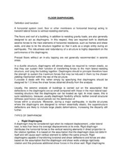
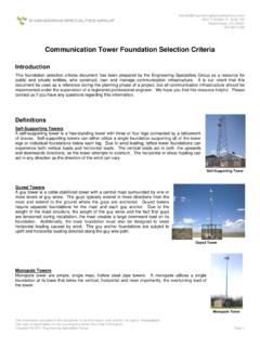
8 The axial loads of the original columns and extra columns are shown in the table 3. Column no. Dead load (kN) Live load (kN) Total service load (kN) Total factored load (kN) C1 765 630 1395 1926 C2 1190 980 2170 2996 C3 1148 945 2093 2889 C4 (maximum) 1785 1470 3255 4494 C5 (extra) 500 300 800 1080 C6 (extra) 450 250 700 940 C7 (extra) 400 200 600 800 C8 (extra) 350 150 500 660 Table 3, all columns loads Design of Raft Foundation Page | 12 Columns Dimensions and Reinforcement: Columns have been designed using the PCA columns. All columns have dimensions of 500 mm by 500 mm with 12 22 as shown in figure 3. This Design of column will resists all columns loads up to the maximum load of 4494 kN Figure 3, Column Design = = ( + ) = = ( (30)(500)(500)+(400)(4562) Pc = 4592 kN > Pu = 4494 kN Design of Raft Foundation Page | 13 Why Raft should be used: If a single square footing need to be designed under the maximum axial load that is occurred in columns type 4.)
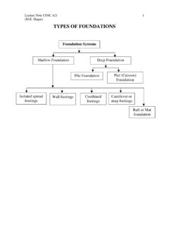
9 This Foundation will be used for a loose sand soil. The properties used in the analysis and the Design of this raft Foundation are shown in table 4. Soil type Loose sand Effective bearing stress for the soil qe=100 kN/m2 Sub-grade modules 20,000 kN/m3 Concrete strength of raft 30 MPa Reinforcement Steel strength 400 MPa Table 4, Properties taken in Raft Design qe=100 kN/m2 Total Maximum Sevice Axial load =1785+1470 kN=3255 kN Area of single sqaure footing = 3255 100= m2 B X B= B= m by 6 m This area is considered to be very big to be excavated under one column. So the raft Foundation will be much efficient and more economical for this Foundation . Design of Raft Foundation Page | 14 Raft thickness: In Raft Foundation , the thickness can be determined by checking the diagonal tension shear that will be imposed in the raft.
10 The maximum ultimate column load will be used in the calculation. = )( ( ) Where, U = factored column load = Reduction factor = = The parameter of the sheared area d = effective depth of raft = Compressive strength of concrete In this Raft, = 4494 kN = MN =4 + = +4 And by using the equation above, the required depth of the raft can be determined. Figure 4, Diagonal tension shear area = )( ( ) ACI-05 +4 )( ( ) 30 +4 2 +4 2 0=4 2+ 0=4 2+ Solving equation for d d = m = 689 mm = 700 mm Thickness of the raft = 700 + 75 + 25 (assumed bar diameter) Thickness = 800 mm Design of Raft Foundation Page | 15 Raft Depth check: One way shear: = ( ) To determine the , the average soil pressure should be determined in the maximum loads stripes.