Transcription of Structural Steel Design, Fabrication, and Construction
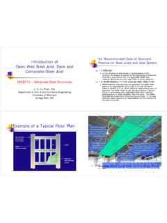
1 Structural Steel Design, fabrication , and Construction Jamie F. Farris, TxDOT Bridge Division October 11, 2011 Design fabrication Construction NSBA/AASHTO Bridge Design Manual - LRFD TxDOT Preferred Practices TxDOT FHWA Consultants Academics Fabricators Detailers Steel Mill reps Texas Steel Quality Council Material Selection Unpainted Weathering Steel Preferred A 709 Grades 50W and HPS 70W More economical Consider location conditions before choosing Use details to prevent concrete staining Prevent Concrete Staining Include drip tabs on all girders Additional options Stainless Steel trays Paint area over Bent Weathering Steel Painted Steel System IV non coastal new Construction System III coastal new Construction More info - See Item 446 of TxDOT Spec Book Span Configuration & Geometry 3 and 4 span continuous Preferred Interior Spans 20-30% longer then End Spans Check uplift at
2 The ends of continuous girders Avoid high skews or major differentials where possible L L to Interior Exterior Exterior Girder Spacing I-girders Limit CL-CL spa to 10 ft Min of 4 girders for vehicular bridge span Tub girders Limit web spacing to 10 ft Min of 3 girders for vehicular bridge span Consider use of PCPs for straight girders I-Shaped Plate Girders Geometric Constraints for Straight Girders Flange Width D/4 Flange Width 15 in in Flange Thick 3 in Web Thick in Min. D in Min. in Min. in Max. Flange Width D/4 Flange Width 15 in 1 in Flange Thick 3 in Web Thick in Min. D in Min. in Min. in Max. Geometric Constraints for Curved Girders Flange Criteria Flange Width Constant Transitions at field splices Top = Bottom Flange Thickness Use 10 ft min length Use only a few sizes In lieu of lateral bracing flange thickness Use similar thicknesses across girders Flange Criteria Flange splices extend thicker flanges beyond theoretical flange splice location Theoretical Location Web Criteria Web Depth Whole inch increments Dapped Ends.
3 No more than 40% of web depth Do not use haunched webs Web Thickness Eliminate need for transverse stiffeners Discourage use of fully stiffened web designs Optimal designs have few sizes Web Criteria Don t use Longitudinal stiffeners unless web depth > 120 in Present fabrication and fatigue problems Field Splices Show in plans as welded Offer bolted splice option Locate at points of DL contraflexure Girder field length ~ 130 ft max Limit shipping width to 6 ft and height to 9 ft Web splice locations at least 10 apart Bolted Field Splices Galvanized bolts for painted Steel 1 , 7/8 , Dia Class A surface conditions Splice PL thickness Add 1/8 to min edge distances in AASHTO LRFD Splice Fill Plates Steel grade specified for girders not available in thicknesses less than 3/8 Allow optional fill plate material (A 606, A 570, etc.)
4 Spec Book A325 vs. A490 Bolts Contractors prefer A325 A325 bolts can be retightened A490 bolts are sensitive to tightening procedures A490 bolts require impact wrenches that might not be available Max Spacing Straight = 30 ft Curved = 20 ft Provide at all end bearings Straight - Set parallel to skew up to 20o. Set radial beyond 20o Curved set radial to girders Diaphragms & X-Frames X-frame Half Pipe Stiffeners Research Project 0- 5701 Gives girders higher buckling capacities Serves as a bearing stiffener Coming soon: Added to SGMD Standard Skewed Bridges Lean On Bracing Research Project 0-1772 Struts transfer forces to 1 or 2 X-frames Minimize LL induced brace forces Reducing number of braces Straight Bridges Stud Connectors Full length of girder Min longitudinal Spa 4d SGMD Standard Not required on top of flange splice plates Bearings Select from TxDOT SGEB standard Triple check bearing seat elevations Avoid costly HLMR, disc, pot bearings Bent Cap geometry Steel Tub Girders Only use if this is the best solution Consider for long, narrow, curved, bridges with tight radius NSBA Practical Steel Tub Girder Design Tub Girders Constant shape Rotated with x-slope Top flange and Web same requirements as I-girder Avoid details more critical than Cat.
5 C Bottom Tension Flange > thick w/t 80 Classified as fracture-critical for 2-girder spans All bottom flange edges extend 2 in + beyond web CL Inspection Access Slabbing and Stripping Top View Girder Elevation Multiple Head Cutting Bed - Strips Out Flanges From Wider Plates Slabbing and Stripping Narrow Gap Electroslag Welding Welding Time Approx. =10- 20% of multiple pass weld Minutes versus Hours Analyze girder system using grid analysis Predict the behavior of girder system once bridge is fully constructed Critical Stages of Stability Girder Erection Before concrete deck placement Research Study 0- 5574 Curved Plate Girder Design for Safe and Economical Construction Justify recommendations in Preferred Practices Create uniformity among analytical requirements of curved I-girders during early stages of Construction Girder erection and concrete slab placement Field Monitoring Parametric Finite Element Modeling Survey of Girder Erection Practices PC Based Analytical tools Research Study 0-5574 Lifting Point Locations Shoring Issues High costs Premature removal Site access issues UT Lift ANALYTICAL TOOLS Spreadsheet Behavior of girder
6 Segments during lifting Determines optimal lift locations Girder deformations Predicts girder twist 3D Finite Element Program Partially constructed girder systems Staged deck placement UT Bridge ANALYTICAL TOOLS National Steel Bridge Alliance AASHTO/NSBA Guidelines for Steel Girder Analysis Shop Detail Drawing Review fabrication Sample Owners Quality Assurance Manual Erection Guide Spec Coating Systems Guide AASHTO/NSBA Final published in Early 2012 23 Chapters including Analysis Load Combinations Splice Design Substructure Design Bearing Design deck Design Design for Fatigue 7 Example Problems Acknowledgements Brian Merrill, TxDOT BRG John Holt, TxDOT BRG Tom Schwerdt, TxDOT CST Mike Hyzak, TxDOT BRG Greg Turco, TxDOT BRG Michelle Romage-Chambers, TxDOT BRG Todd Helwig, University of Texas Karl Frank, Hirschfeld Industries Jason Stith, Michael Baker, Inc University of Texas Researchers TxDOT BRG Construction Section