Transcription of STRUCTURAL WELDED WIRE REINFORCEMENT
1 STRUCTURAL WELDEDWIRE REINFORCEMENTWIRE REINFORCEMENT INSTITUTE, Main Street Suite 300 Hartford, CT 06103 (800) 552-4 WRI [4974] Set in ConcreteWIRE REINFORCEMENT INSTITUTE MANUAL OFSTANDARD PRACTICE12 Manual ofStandard PracticeStructural WeldedWire ReinforcementIncludes latest developments on use of WWRunder American Concrete Institute Building Code 318 Prepared under direction of the technical committees of theWire REINFORCEMENT Institute, IncorporatedPhoto Captions for Front Cover Photos1 Jacking bars are used to properly position WWRafter ready mix trucks leave and before screeding takes Properly positioning two layers of WWR onsteel Main Street, Suite 300 Hartford, CT 06103 Phone: (800) 522-4 WRI [4974]Fax: (860) of Wire Description .. Size Designation .. and Process .. Quantity Requirements .. Sizes .. Project Needs.
2 And Coating .. Strength (elongation test criteria) .. Shear Strength .. Code Requirementsfor Reinforced Concrete (ACI 318).. area Table ..19-20 Development & Splice Lengths Deformed WWR ..21-22 Development & Splice Lengths Plain WWR ..23-24 Wire Size Comparison Tables .. , Shipping and ( mass ) ( mass ) Estimating Copyright July 2001 Wire REINFORCEMENT Institute, 6th Edition Last Printing, 1999 Printed in manual is furnished as a guide for the selection of WELDED wire REINFORCEMENT with theunderstanding that while every effort has been made to insure accuracy, neither the Wire ReinforcementInstitute, Inc., nor its member companies make any warranty of any kind respecting the use of the manualfor other than informational wire REINFORCEMENT (WWR) is a prefabricatedreinforcement consisting of parallel series of high-strength, cold-drawn or cold-rolled wire WELDED togetherin square or rectangular grids.
3 Each wire intersection iselectrically resistance- WELDED by a continuous automaticwelder. Pressure and heat fuse the intersecting wires intoa homogeneous section and fix all wires in their properposition. Plain wires, deformed wires or a combination ofboth may be used in plain wire reinforcment bonds to concrete by thepositive mechanical anchorage at each WELDED wire inter-section. WELDED deformed wire utilizes deformations pluswelded intersections for bond and structures are being successfully and econom-ically reinforced with high-strength, uniformly distributedwires in WWR. The smaller diameter, closely-spacedwires of WWR provide more uniform stress distributionand more effective crack control in slabs and walls. Thewide range of wire sizes and spacings available makes itpossible to furnish the exact cross-sectional steel arearequired.
4 The WELDED crosswires hold the reinforcementin the proper position, uniformly spaced. The ease andspeed with which WWR can be handled and installedconsiderably reduces placing time, resulting in reducedcost. Reduced construction time is of particular benefit tothe owner by affording earlier occupancy and reducingtotal (project) cost. Material savings can be realized byspecifying WWR with higher yield strengths as recog-nized by ACI 318 and ASTM. Consult various manufac-turers for their high-strength manual provides WWR product information, materi-al specifications, design and detailing requirements, andvarious tables and design aids for those interested in thedesign and construction of reinforced concrete a shear cage of WELDED wire REINFORCEMENT in a concrete girder for a sports Wire Reinforcement1 Section at typical weld showing complete fusion of Item DescriptionIn the WELDED wire industry, an item is the term used todesignate a complete unit of WWR as it appears on anorder Wire Size DesignationIndividual wire (plain and deformed) size designations arebased on the cross-sectional area of a given wire.
5 Gagenumbers were used exclusively for many years. The industrychanged over to a letter-number combination in the 1970 prefixes W and D are used in combination with anumber. The letter W designates a plain wire and the letter D denotes a deformed wire. The number following theletter gives the cross-sectional area in hundredths of asquare inch. For instance, wire designation W4 would indi-cate a plain wire with a cross-sectional area of sq. in.;a D10 wire would indicate a deformed wire with a cross-sectional area of sq. in. The size of wires in weldedwire mesh is designated in the same manner. This systemhas many advantages. Since the engineer knows the cross-sectional area of a wire and the spacing, the total cross-sectional area per foot of width can easily be instance, a W6 wire on 4 inch centers would provide 3wires per foot with a total cross-sectional area of sq.
6 Foot of describing metric wire, the prefix M is added. MWdescribes metric plain wire and MD metric deformedwire. The wire spacings in metric WWR are given in mil-limeters (mm) and the cross-sectional areas of the wiresin square millimeters (mm2).Nominal cross-sectional area of a deformed wire isdetermined from the weight ( mass ) per foot of wire rather than the StyleSpacings and sizes of wires in WWR are identified by style. A typical style designation is:6 x 12 W12 x W5 This denotes a unit of WWR in which: Spacing of longitudinal wire =6 (152mm) Spacing of transverse wires=12 (305mm) Size of longitudinal wires=W12 ( sq. in.) (77mm2) Size of transverse wires=W5 (.05 sq. in.) (32mm2)Thus, the style for the sample above would be expressedmetrically as 152 x 305 MW77 x MW32. A weldeddeformed wire style would be noted in the same mannerby substituting the prefix D for the W.
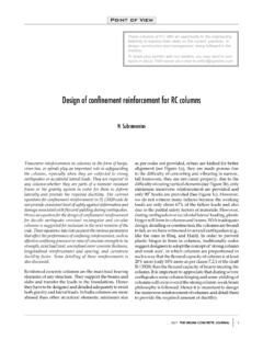
7 Note that style gives spacings and sizes of wires only and does not pro-vide any other information such as width and length with non-uniform wire spacings is available. In thiscase, special information is added to the style designa-tion to describe the is very important to note that the terms longitudinal andtransverse are related to the manufacturing process anddo not refer to the relative position of the wires in a con-crete structure. The WWR manufacturing process is dis-cussed in detail in section Transverse wires areindividually WELDED at right angles as the reinforcementadvances through the welder. In some WWR machines,the transverse wire is fed from a continuous coil; inothers they are precut to length and hopper fed to thewelding 2 End Overhangs Thesum of the end overhangsshould equal onetransverse wire otherwisespecified, each endoverhang equals one-halfof a transverse space.
8 Longitudinal wireTransverse wireFigure 1 NomenclatureLengthOverall WidthWidthSide Overhangs may bevaried as required and donot need to be lengths limitedonly by overall sheet widthIndustry Method of Designating Style:Example 6 x 12 W12 x W5 Transversewire sizeLongitudinalwire spacingTransversewire spacingLongitudinalwire DimensionsDescription of width, length and overhang dimen-sions of sheets follow:Width=Center to center distance between outside longitudinal wires. This dimen-sion does not include Overhang =Extension of transverse wires beyond centerline of outside longitudinalwires. If no side overhang is specified, WWR will be furnished with over-hangs on each side, of no greater than 1 inch (25 mm). Wires can be cut flush (no overhangs) specified thus:(+0 , +0 ). When specific overhangs are required, they are noted thus:(+1 , +3 ) or (+6 , +6 ).
9 Overall Width = Width including side overhangs, in. (or mm). In other words the tip-to-tip dimension of transverse = Tip-to-tip dimension of longitudinal wires. Whenever possible this dimen-sion should be an even multiple of the transverse wire spacing.[The length dimension always includes end overhangs.]End Overhangs = Extension of longitudinal wires beyond centerline of outside transverse otherwise noted, standard end overhangs are assumed to be required and end overhangs need not bespecified. Non-standard end over-hangs may be specified for specialsituations; preferably the sum of the two end overhangs should equal the transverse wire spacing.(Above) Inner and outer vertical face of wall following example of WELDED wire REINFORCEMENT items illustrates how a typical order using the nomenclaturedescribed might appear:ItemQuantityStyleWidthSide OverhangsLengths11000 Sheets12 x 12 W11 x W1190 (+6 , +6 )15 -0 2150 Sheets6 x 6 W4 x W460 (+0 , +0 )20 -0 3500 Sheets6 x 12 D10 x D696 (+3 , +3 )17 -0 A sample metric order would appear as follows:ItemQuantityStyleWidthSide OverhangsLengths11000 Sheets305 x 305 MW71 x MW712286mm(+152, +152) Sheets152 x 152 MW26 x MW261524mm(+0, +0) Sheets152 x 305 MD65 x MD392438mm(+76, +76) & Availability Manufacturing ProcessThe wire used in WELDED wire REINFORCEMENT is producedfrom controlled-quality, hot-rolled rods.
10 These rods arecold-worked through a series of dies or cassettes toreduce the rod diameter to the specified diameter; thiscold-working process, increases the yield strength of thewire. Chemical composition of the steel is carefullyselected to give proper welding characteristics in additionto desired mechanical is produced on automatic welding machines whichare designed for long, continuous operation. Longitudinalwires are straightened and fed continuously through themachine. Transverse wires, entering from the side or fromabove the welder, are individually WELDED at right anglesto the longitudinal wires each time the longitudinal wiresadvance through the machine a distance equal to onetransverse wire is manufactured with the following variables:1. Longitudinal wire spacing2. Longitudinal wire size3. Width4. Side and end overhangs5.