Transcription of Study on Maximum Flow Rates and Sizing Method of …
1 CIB W062 Symposium 2006 1 Study on Maximum Flow Rates and Sizing Method of Overflow Pipes in water Tanks Wang (1), F. Kiya (2), K. Maejima (3), S. Yanagimura (4), C. Yoneda (5) (1) SUGA Co., Ltd., Research and Development Center, (2) Kanagawa University (3) Morimura & Associates, Ltd. (4) SUGA Co., Ltd., Research and Development Center (5) SUGA Co., Ltd., Research and Development Center Abstract When examining the standard of the air-gap in open tanks with overflow pipes, it is necessary to determine the height of the highest water level and Maximum capacity of overflow pipe in tanks.
2 However, it is not cleared not only to determine the height and the capacity, but also to decide the size of overflow pipe. Therefore, the experimental Study was carried out for the purpose to obtain them. In this paper, it was reported the experiment result concerning the FRP water tank with overflow pipe of inside diameters 50 mm and 100 mm. As a result, empirical formulae of the height by incoming flow Rates and inside diameters, and the Maximum flow rate of overflow pipes are shown. Moreover, methods to decide the size of overflow pipes are proposed. Keywords Experiment, Air-Gap, water Level Change, Overflow, Maximum Flow Rate of Overflow Pipe, Sizing Method of Overflow Pipe 1.
3 Introduction Setting the air-gap to prevent the back-siphonage is a simple and reliable Method . There are the standard of the air-gap in each country. In Japan, a Study on small size pipes by diameters 9 mm to 30 mm by Shinohara et al. had been carried out, and the standard published in SHASE-S206-2000 which is based on the result is the standard of SHASE (The Society of Heating Air-conditioning and Sanitary Engineering of Japan). Experimental grounds on the overseas standards such as the United States and Europe are not clear; the experiment of the one to exceed diameters 40 mm or 50 mm was not CIB W062 Symposium 2006 2 carried out in any case.
4 As the standard of the air-gap, it is required that overflow pipe have enough capacity. However, it is general to assume the size of the overflow pipe to be two size-ups of the diameter of water supply pipe, but clear grounds have not been shown. It is necessary to confirm this validity and the drain capacity of overflow pipe. To secure the air-gap in water tank with an overflow pipe (hereinafter referred to as water tank), it is necessary to accumulate the basic data for examination the standard of air-gap, such as the Maximum drain flow rate and the highest possible water rising level in water tank.
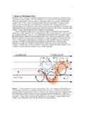
5 The authors carried out the experiment on FRP water tank with overflow pipe of the inside diameters 50 mm and 100 mm. In this paper, the experiment result on the Maximum flow rate, the water level change situation in a water tank, and the Method of Sizing an overflow pipe are presented. 2. Experiment Overview Experiment equipment The water tank used to the experiment was made of FRP, the size was 1000 1000 2 000 mm, and the overflow pipes of diameters 50 mm and 100 mm were installed on each side of the open water tank. The experiment apparatus is shown in Figure 1, and the specification of the experiment materials is shown in Table 1.
6 To make easy for experiment, the ball valves were installed in each overflow pipes, and switching to each pipe in each experiment. Moreover, the horizontal sectional area of this experiment water tank was assumed to be m2, because it was estimated that the speed of water level rising from the base level and time until stabilizing the water level were different for a different sectional area, and requested water level rising relation to flow rate and the drain capacity of overflow pipe were not change. 20001000 Break tank100050mm65mm1000M500 LoggerAMPO verflow pipe, 100mm(Offset piping type)Bypass pipe(regulation the flow of water supply) water supply pipe, 65mmSupersonic wave type flow meterWater supply pump(Control by inverter)Supersonic wave type displacement sensorVertical overflow outlet typeExperiment water tankDiffusing pipeOverflow pipe, 50mmBa ll va lve(Offset piping type)PC(If the piping of the internal dottedline parts are detached, it becomes ahorizontal overflow outlet type)
7 Figure 1 Experiment apparatus CIB W062 Symposium 2006 3 Ta b l e 1 Specification of the experiment materials Item Specification Material made of FRP, single panel type water tank for experiment Size:1000 1000 2000 mm Material: made of FRP, single panel type Break tank Size:1000 1000 1000 mm Material PVC Bell mouth Pipe diameter 100 mm, bell mouth part 145 mm 50 mm, bell mouth part 75mm Material VP Overflow pipe Diameters:100 mm 50 mm water supply pump Capacity: 65 A 500 L min 10 m kW Inverter 200V kW 0 50 Hz Highly accurate supersonic wave type displacement sensor Time base range:80 300 mm Resolution: mm Data logger 16ch Sampling interval: s Supersonic wave type flow meter Application diameter: 13 100 Time base range:-32 0 32 m/s It is necessary to keep the stability of the surface of the water to measure the water level change in the water tank when experimenting.
8 Then, the diffusing pipe was installed to connected the water supply pipe (diameter 65 mm) in the tank, the sectional area of the diffusing pipe is 4 times wide of it of the water supply pipe, and the result, the flow velocity in the diffusing pipe has been decreased to about 1/4. In addition, the SUS punching board was installed in the upper layer on the diffusing pipe at the direction of the water flow cross section, and the stabilization of the surface of the water in the tank was achieved. As a result, the water level change in the tank was less than mm when water was to be supplying, and the accuracy of the experiment was improved.
9 Experiment conditions Two kinds of outlet types of each overflow pipe (the vertical overflow outlet type and the horizontal overflow outlet type) were set; piping routes was set to each overflow outlet by a straight piping and a offset piping. Table 2 shows the combination and each classification of the overflow outlet type and the piping route of the overflow pipes. Moreover, the piping route and the length on each classification in the vertical overflow outlet type and the horizontal overflow outlet type are shown in Figure 2 and Figure 3. The flow rate was changed to 8 types of overflow pipes shown in Table 2 respectively, the experiment on 112 patterns in total was carried out, and water levels rising in the tank and the Maximum drain flow Rates of the overflow pipe were confirmed.
10 The flow Rates in each experiment pattern are explained in the experiment result. Experiment Method water was supplied from the water supply pump to the experiment water tank, the water level change in the tank was measured by the supersonic wave type displacement sensor, the flow rate and the water level change data were recorded on the personal computer. The water supply flow rate was set according to overflow diameters by 30 780 L/min CIB W062 Symposium 2006 4 ( Maximum capacity of the water supply pump), and the flow was regulated by installed inverter control of the pump and manual control the ball valves in water supply bypass pipe.