Transcription of Supplementary Notes: Stereonets
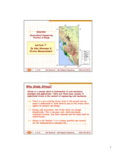
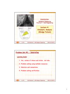
1 11 of 18 Erik Eberhardt UBC Geological Engineering EOSC 433 EOSC433: Geotechnical Engineering Practice & DesignSupplementary Notes: Stereonets2 of 18 Erik Eberhardt UBC Geological Engineering EOSC 433 Discontinuity MappingWindow mappingScanline mappingHudson & Harrison (1997)23 of 18 Erik Eberhardt UBC Geological Engineering EOSC 433 Discontinuity Mapping Remote SensingMahet al.(2013)3-D laser imagingis an emerging tool for discontinuity mapping. Acquisition is performed at a safe distance, including for inaccessible areas. Millions of high accuracy 3D data points are acquired in Cartesian space, and processed efficiently by automatic algorithms, leading to robust estimates of joint dipand dip of 18 Erik Eberhardt UBC Geological Engineering EOSC 433 Discontinuity MappingWyllie & Mah (2004)35 of 18 Erik Eberhardt UBC Geological Engineering EOSC 433 Stereographic ProjectionStereographic projection allows 3-D orientation data to be represented and analyzed in 2-D.
2 This projection consists of a reference sphere in which its equatorial plane is horizontal, and its orientation fixed relative to north. The equatorial projectionis the one generally favoured for plotting and analyzing discontinuity most common Equatorial projection is the equal area stereonet (aka Schmidt or Lambert stereonet). 6 of 18 Erik Eberhardt UBC Geological Engineering EOSC 433 Stereographic ProjectionEqual-area stereonetsare used in structural geology because they present no statistical bias when large numbers of data are plotted. On the equal-area net area is preserved so, for example, each 2 degrees polygon on the net has the same structural geology the stereonet is assumed to be a lower-hemisphereprojection since all structural elements are defined to be inclined below the horizontal.
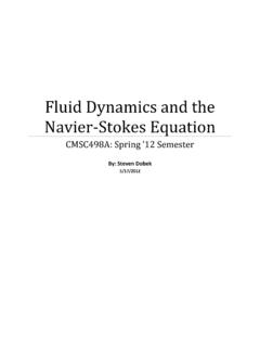
3 47 of 18 Erik Eberhardt UBC Geological Engineering EOSC 433 Stereographic ProjectionFor a plane( a discontinuity surface), its intersection with the lower half of the reference sphere defines a unique line on the stereonet (in the shape of a circular arc called a great circle . To plot the great circle, the dip direction and dip must be & Mah (2004)8 of 18 Erik Eberhardt UBC Geological Engineering EOSC 433 Stereonets : PreparationNorthEWSA lways begin by labelling your stereonet!! -North, south, east, west- Lower/upper hemisphere- Equal area/equal angleLower hemisphereEqual areaPlotting is done on transparent paper laid over the stereonetthat can be rotated around a thumb tack poking up at the center of the net. A tick mark coinciding with the 0 degree mark is labeled N, with E, S and W marked at 90, 180 and 270 degrees, of 18 Erik Eberhardt UBC Geological Engineering EOSC 433 Stereonets : Plotting a Plane (Dip Direction)Example:68/219 (dip/dip direction)First mark off the dip direction (in this case, 219 ) on a piece of tracing paper overlying the (1985)10 of 18 Erik Eberhardt UBC Geological Engineering EOSC 433stereonettracing paper pinStereonets: Plotting a Plane (Dip Direction)Example:68/219 (dip/dip direction)20 40 0 68 Count off the dip angle and mark it on the tracing paper.)
4 Then draw in the great circle for the specified plane. Rotate the tracing paper until the mark you made is lying on the east-west diameter of the stereonet. 611 of 18 Erik Eberhardt UBC Geological Engineering EOSC 433 Stereonets : Plotting a Plane (Dip Direction)Your tracing paper should now look as follows: NEWS68/219 Lower hemisphereEqual areaExample:68/219 (dip/dip direction)12 of 18 Erik Eberhardt UBC Geological Engineering EOSC 433 Lower hemisphereEqual areaStereonets: Plotting a Plane (Dip Direction)Now try adding:20/090 (dip/dip direction)45/165 90/000 10/320 NEWS20/090 45/165 10/320 68/219 90/000 713 of 18 Erik Eberhardt UBC Geological Engineering EOSC 433 Rotate the tracing paper back to North, and measure the trend of the line. Intersecting PlanesWhen two planes intersectthey define a line, which is common to both planes.
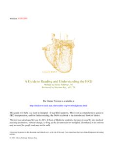
5 The trendand plungeof this line can be read directly off the the tracing paper until the intersection of the two planes lies on the east-west diameter of the stereonet. Measure the plunge of the line of intersection and add an arrow pointing in the direction of plunge. 14 of 18 Erik Eberhardt UBC Geological Engineering EOSC 433 Pole PlotsA pole perpendicular to a plane surface intersects the outer bowl as a point. In many situations it is more convenient to plot the pole of a plane rather than the great circle. The pole represents the line that is perpendicular to the plane. Since the intersection of a line with the lower hemisphere is a point, the pole will always plot as a point, and will always have an attitude measured as a plunge and of 18 Erik Eberhardt UBC Geological Engineering EOSC 433 The pole is the normal to the plane ( the vector that is perpendicular to the plane).
6 Stereonets : Plotting a PoleThe pole(or normal vector ) of a plane allows the plane to be represented on the stereonet as a single point. Pole plots are a convenient way to examine the orientation of a large number of discontinuities, such as that measured during a discontinuity scanline & Mah (2004)90 When the tracing paper is rotated so that the dip direction is aligned with the east-west diameter, the pole is plotted 90 from the edge of the Great Circle. 16 of 18 Erik Eberhardt UBC Geological Engineering EOSC 433 Stereonets : Plotting a PoleLower hemisphereEqual areaNEWS20/090 45/165 10/320 68/219 90/000 Try plotting the poles to our earlier example planes:68/219 (dip/dip direction)20/090 45/165 90/000 10/320 As a guide in helping you visualize poles, planes with a shallow dip will have poles that plot near the centre, and planes that are steeply dipping will have poles that plot near the circumference of the of 18 Erik Eberhardt UBC Geological Engineering EOSC 433 Stereonets : out all of the exhilarating stereonet action on YouTube: Setting up a stereonet: a plane: a pole: 18 of 18 Erik Eberhardt UBC Geological Engineering EOSC 433 Lecture ReferencesHudson, JA & Harrison, JP (1997).
7 Engineering Rock Mechanics An Introduction to the Principles .Elsevier Science: , J, Samson, C, McKinnon, SD & Thibodeau, D (2013).3D laser imaging for surface Journal of Rock Mechanics & Mining Sciences58: 111 117 Priest, SD (1985).Hemispherical Projection Methods inRock Mechanics. George Allen & , DC & Mah, CW (2004).Rock Slope Engineering (4thedition). Spon Press: London.