Transcription of SURFACE FINISH GUIDELINES
1 FINDING THE OPTIMUM SURFACE FINISHTo achieve the optimum seal performance it is critical for themating hardware SURFACE FINISH to have defined characteristicsthat address the roughness, directional orientation or lay andhardness for reliable seal efficiency and life. As the Aerospaceindustry transitions from the traditional hard chrome platingtoward the use of HVOF (High Velocity Oxygen Fuel) coatings, thedefinition of an optimum SURFACE FINISH has also recently hard chrome plating had been effectively utilizedfor dynamic surfaces as the traditional coating method. To thisend, Aerospace seal gland specifications have been publishedwhich include SURFACE FINISH requirements that are proven to becomplimentary to efficient seal performance, primarily when usedwith established elastomeric and PTFE contact is important to recognize the distinct differences between hardchrome plating and HVOF coating.
2 Most notable is the manner in which chrome and HVOF interact with seals and bearings in dynamic applications. Experience with chrome has shown that with increasing time in service, the chrome SURFACE FINISH will polish and become smoother. Conversely, HVOF surfaceshave been found to remain relatively constant regardless of theaccumulation of dynamic cycles with seals and bearings. As aresult, Greene, Tweed has established distinct recommendationsfor chrome and HVOF-coated OF SURFACE FINISH PARAMETERSG reene, Tweed s recommendation for SURFACE FINISH utilizes thedefinitions of the parameters as found in ISO 4287 for chromeplated or coated or finished information below references the Rp, Rz and Rmr surfaceparameters. This information is intended for reference only, andthe specific ISO standard should be consulted for more This parameter is a measure of the largest peak and can be used to gauge the potential aggression of the HVOF surfaces are most generally comprised of tungsten and carbide particles, a low Rp is recommended toassure that no irregularly high peaks are present that could act to score or slice the seals and This is a measure of the average peak to valley height of thesurface.
3 Since boundary layer lubrication present on the surfacecan be beneficial to reduce the friction and corresponding wearon the seal, the Rz characteristic provides an indication of thesurface s potential to maintain the desired lubrication to the originally known as the 10 Point Height, this characteristic123 SURFACE FINISH GUIDELINESP arameter Definition of the Parameter ISO 4287: 1997 RaThe arithmetic mean of a SURFACE FINISH profile within asampling lengthRpThe largest peak height of a SURFACE FINISH profile within asampling length measured from the mean lineRzThe average of the sums of the largest valley depth to thehighest peak of a SURFACE FINISH profile within a samplinglengthRmr (Tp)The ratio of the material length at a specified depth for asurface FINISH profile 2007, Greene, Tweed all rights reserved All trademarks are property of their respective FINISH \ product datahas recently been re-defined by the ISO specification.
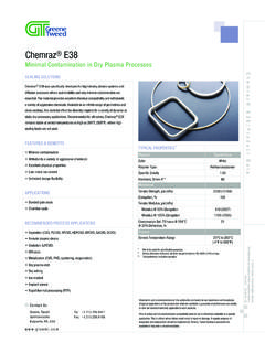
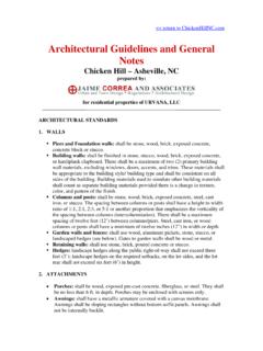
4 Simply, it isnow the average of the highest peak to the deepest valley of fivesampling lengths taken across an evaluation length of a surfaceprofile (1997) = 1/5 { i},where Zi= (Pi+Vi) for each sampling lengthRmr This parameter provides information on the relative materialratio at a specific evaluation depth. In many applications this infor-mation is used to evaluate the load bearing capacity of the surfaceprofile. Along with the other SURFACE FINISH parameters, Greene, Tweeduses Rmr (tp) to determine the consistency of the SURFACE profile. Evaluation of Rmr (tp) is somewhat misunderstood. To clarify, thesurface FINISH profile is evaluated by a generated Abbott-Firestonecurve. This curve plots the percentage of material present in asurface profile based on the depth from the highest peak. Using the Abbott-Firestone curve, the parameters COand C1determine the evaluation depth for determining the Rmr (tp)DYNAMIC CHROME SURFACE FINISH RECOMMENDATIONSE lastomeric Contact SealsGreene, Tweed s recommendation for elastomeric contact seals coincides with the specified SURFACE FINISH definitions of the governing Aerospace specifications MIL-G-5514, AS4716 and AS4832.
5 Ra = 16 inches ( meters) MaximumNote: In accordance with the previous revision of Aerospace Specification AS4716, Ra = 8 to 12 inches ( to meters) is considered optimum for elastomeric contact recommendation balances the two important aspects of desirablesurface characteristics for elastomeric contact seals the promotionof boundary layer lubrication between the seal and the hardwaresurface and minimal aggressive wear between the hardware andthe elastomer seal is important to note that there has been some consideration in the Aerospace industry to expand upon the recommendationscurrently found in the Aerospace specifications by controlling othersurface FINISH parameters beyond Ra. This is allowable with theadditional parameters defined based on finishing and processingcontrols and historical performance data. Note, however, thatconsideration regarding the possible impact that the control ofthese additional parameters may have on other system productionlead time.
6 Economics should be balanced against the net benefitachieved by specifying parameters other than Ra. Acknowledgingthat the chrome SURFACE FINISH is likely to polish/change after ashort time in service, the long-term, net positive effect of controllingadditional parameters for chrome, may be PEAKDEEPEST VALLEYABBOTT-FIRESTONECURVE COis a set percentage belowthe highest peak to eliminate possible measurement error C1is a defined distance beneathCOand defines where the surfaceprofile is evaluated Where C1intersects the X axis is the stated Rmr (tp) for a surfaceprofile 2007, Greene, Tweed all rights reserved All trademarks are property of their respective DS-US-AS-032surface FINISH \ product PTFE Cap/Contact SealsDue to the fact that PTFE materials are inherently self-lubricating,the need for boundary layer lubrication between the seal and thehardware is less critical than with elastomeric contact seals.
7 As aresult, hard chrome plating should be finished in such a manneras to reduce the boundary layer lubrication while still promotinga less aggressive SURFACE FINISH topography. As a result, Greene,Tweed recommends:Ra = 4 to 8 inches ( to meters)With the use of both elastomeric and PTFE contact seals it isimportant to obtain a neutral grain orientation to the machinedsurface. Many finishing techniques such as single point turning,grinding, honing, roller burnishing and polishing are used in the manufacturing process. A process that induces a directionalorientation to the structure of the SURFACE can negatively influencethe leakage and wear behavior of the selected seal and should be OF THE MATING SEALING SURFACE A dynamic hardware SURFACE hardness that is generally below 42 HRCwill promote seal-induced polishing and wear to the mating metalsurface and also inhibit the use of higher performance, wear-resistant-reinforced PTFE seal materials engineered for longer service surfaces with hardness greater than 42 HRC generallyallow the selection of optimum seal materials for a balancedendurance life APPLIED COATINGS, DYNAMIC SURFACE FINISHRECOMMENDATIONSIn conjunction with SAE as well as the industry sponsored HCAT(Hard Chrome Alternative Team), Greene, Tweed has developed anoptimum dynamic SURFACE FINISH profile recommendation for usewith HVOF coatings.
8 It is critical to note that HVOF behaves verydifferently than chrome because it does not polish over time andthe coating has been shown to remain in its originally finished con-dition throughout its time in service. Additionally, since the mostcommonly recommended HVOF powders consist of both tungstenand carbide particles, both of which are known to be very denseand potentially aggressive to seals and bearings, it is critical thatthe proper SURFACE FINISH be defined and verified for dynamic sealapplications. Greene, Tweed recommends the following SURFACE FINISH for HVOF:Ra = 4 inches ( meters) MaximumRp = 8 inches ( meters) Maximum Rz = 40 inches ( meters) Maximum Rmr = 70 to 95% at C0 = 5%, C1 = RzThe definitions of the above characters have been explained previously and are determined by ISO 4287 and ISO COATING RUNOUT/LEAD-INRECOMMENDATIONSE xperience has shown that the blending and runout of coatingand plating also requires proper attention in order to minimizethe possibility of seal installation difficulty or start-up efficiencyconcerns.
9 Therefore, we recommend the following:Chrome RunoutChrome runout has been established to terminate on a geometricfeature of the hardware, usually a radius or chamfer. While thisapproach has been used successfully in many aircraft system, it iscritical that the runout band be smooth and free from pitting orraised inclusions. Pits or raised features in the runout band can bepotentially aggressive to seals and bearings, causing axial scoringor tearing in the seal material. In the case of reinforced PTFE capseals, scoring the seal material during installation is the leadingcause of start-up wetting on new systems, with the wetting continuinguntil the system accumulates sufficient cycles under load to effectivelybreak-in the scored sealing cap. 2007, Greene, Tweed all rights reserved All trademarks are property of their respective FINISH \ product dataHVOF Runout In order to promote the proper installation of seals on HVOF, it isrecommended that care be taken with the proper specificationand manufacture of the coating runout onto the parent materialof the hardware.
10 Since HVOF utilizes hard, dense particles such astungsten and carbides, greater care in the preparation of therunout needs to be taken as compared to traditional chrome there is currently no established industry specification to guidethe preparation of HVOF runout, some common criteria are ) Long fade out is preferred Traditional chrome runout hasbeen specified as a finite distance from a chamfer or radius,with the typical runout less than inch. For HVOF, muchlonger blending of the coating is preferred, with the amount ofthe blend to be determined by the manufacturing methodologyand hardware ) Hardware geometry Traditional chrome runout was concurrentwith a chamfer or radius in the hardware geometry. It is nowrecognized as beneficial, where possible, to incorporate a longtaper in the parent material geometry to facilitate the runoutand fade out of the coating. The HVOF coating can be featheredalong the tapered geometry to create a more consistent, benignrunout.