Transcription of Surface-mountFuses Fundamentals - Mouser Electronics
1 75 Surface-mount Fuses Fundamentals11 Surface-mount FusesFundamentalsOverviewTE Circuit Protection offers the widest selection of Surface-mountFuses available for addressing a broad range of overcurrentprotection applications. Helping to prevent costly damage andpromote a safe environment for electronic and electricalequipment, our single-use chip fuses provide performance stabilityto support applications with current ratings from .5A up to Circuit Protection also offers the telecom FT600 fuse fortelecommunications applications. This telecom fuse helps complywith North American overcurrent protection requirements,including Telcordia, GR-1089, TIA-968-A (formerly FCC Part 68),and UL60950 3rd Design for Chip FusesThe multi-layer design has the benefit of exposing more fuseelement surface area to the glass-ceramic absorption the fuse elements open, there is more material for thevaporizing fuse metals to absorb into, resulting in a very efficientand effective quenching of the fuse 1 compared the multi-layer design of our SFF fuses withstandard glass coated designs.
2 The glass coated designs rely onthe coating on only one side of the fuse element to absorb thevaporizing fuse material when it opens. Therefore, there is muchless absorption material available to absorb the fuse metals. Theresult can be prolonged arcing and possible coating 2 shows how the absorption characteristics of the twodesigns differ. The multi-layer design indicates a clean separationwith the fuse element evenly diffusing into the surroundingceramic substrate. In the glass coated design, the elementdiffusion takes place in a small portion of the device and is onlyabsorbed by the glass material directly above the area of FuseElementsSubstrateMaterialSingle FuseElementSingle-layer Glass Coated DesignMulti-layer DesignGlassCoatingFigure 1 Figure 2 FaultZonesMulti-layerDesignSingle-layerG lassCoatedDesignWire-In-Air Design for 2410 SFV FusesThe 2410(6125) is a Wire-In-Air SMD Fuse which is very suitablefor secondary level over current protection 3 compared our straight wire element design 2410 SFVfuses with normal corrugating wire design fuse.
3 The straight wireelement in air performs consistent fusing and cuttingcharacteristics together with excellent inrush currentwithstanding PCB assembly technology into 2410 SFV fuses designand manufacture, we achieved on lead free completely and noend cap falling off risk comparing with traditional ceramic bodywith end cap fiber enforcedepoxy bodyCeramic bodyCorrugate wire elementEnd cap plated with TinStraight wire elementCopper terminalplated with Ni and TinFigure 37611 Pulse Cycle DeratingOnce the I2t value for the application waveform has beendetermined, it must be derated based on the number of cyclesexpected over the system lifetime. Since the stress induced by thecurrent pulse is mechanical in nature, the number of times thestress is applied has significant bearing on how much deratingmust be applied to the fuse rating. Figure 5 presents the currentpulse derating curve for our surface-mount chip fuses up to100,000 Selection FlowchartHowever, the basic considerations for fuse selection are shown in the flowchart presented in Figure 6.
4 Following this flow chartwill help you select a fuse best suited for your application Fuse Pulse Derating Curve100100010000100000100%10%Number of Pulses% of Minimum I2tFigure 5 Step 1 Determine Steady StateFuse Current RatingStep 2 Determine PulseWaveform byCalculating I2tStep 3 Apply PulseCycle DeratingStep 4 Apply PulseTemperatureDeratingStep 5 Apply Deratingfor Variance inthe CircuitStep 6 Select Fuse CurrentRating for PulseEnvironmentStep 7 Select Fuse Current Rating(use higher value between Step 1 and Step 6)Step 8 Check Voltage RatingApply Standard SteadyState Derating (75%)[Ifuse ]ApplyTemperature Derating[Ifuse ]Steady StateFuse CurrentRatingFigure 6 Selecting Surface-mount FusesFuse selection seems straightforward, in that, you pick one which has a current rating just a bit higher than your worstcase systemoperating current. Unfortunately, it s not that simple.
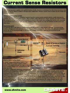
5 There are derating considerations for operating current and applicationtemperature. Turn-on and other system operations (like processor speed changes or motor start up) cause current surges orspikes that also require consideration when selecting a fuse. So selecting the right fuse for your application is not as simple asknowing the nominal current drawn by the DeratingA fuse is a temperature sensitive device. Therefore, operating temperature will have an effect on fuse performance and temperature should be taken into consideration when selecting the fuse current rating. The Thermal Derating Curve forsurface mount fuses is presented in Figure 4. Use it to determine the derating percentage based on operating temperature andapply it to the derated system SeriesThemal Derating Curve2410 SeriesTemperature Effect On Current Rating-55-55-35-15525456585105125-45 -35 -25 -15 -5 5 15 25 35 45 55 657085 95 105 115 1251101009080706050403020100110105100959 08580757065605550 Maximum Operating Temperature ( C)Maximum Operating Temperature ( C)% of Carrying Current Capacity88%% De-ratingFigure 477 Surface-mount Fuses Pulse Tolerant Chip Fuses11 Pulse Tolerant chip fuses has high inrush currentwithstand capability and provide overcurrent protectionon DC power systems.
6 Silver fusing element, monolithicand multilayer design provides strong arc RoHS-compliant surface-mount devices facilitatethe development of more reliable, high performanceconsumer Electronics such as laptops, multimediadevices, cell phones, and other portable Electronics . High inrush current withstanding capability Ceramic Monolithic structure Silver fusing element and silver termination withnickel and tin plating Excellent temperature stability Strong arc suppression characteristics Lead free materials and RoHS compliant Halogen free(refers to: Br 900ppm, Cl 900ppm, Br+Cl 1500ppm) Monolithic, multilayer design High-temperature performance -55 C to +125 C operating temperature range Laptops Digital cameras Cell phonesBenefitsFeaturesApplications Printers DVD players Portable Electronics Game systems LCD monitors ScannersSurface-mount FusesPulse Tolerant Chip FusesNEWNENENENENENENENENENENENEWWWWWWWW WWWWNEW78 RoHS Compliant, ELV CompliantHFHalogen Free11% of rated currentClear time at 25 C100%4hours(min.)
7 200%1seconds(min.) 60seconds(max.)1000% (min.) (max.)0603 SFP100F/32-2 32 500603 SFP150F/32-2 32 500603 SFP200F/32-2 32 500603 SFP250F/32-2 32 500603 SFP300F/32-2 32 500603 SFP350F/32-2 32 500603 SFP400F/32-2 32 500603 SFP450F/32-2 32 500603 SFP500F/32-2 32 501206 SFP100F/63-2 501206 SFP150F/63-2 501206 SFP200F/63-2 501206 SFP250F/32-2 501206 SFP300F/32-2 501206 SFP350F/32-2 501206 SFP400F/32-2 501206 SFP450F/32-2 501206 SFP500F/32-2 50*Measuredat 10%ofratedcurrentand25 Cambienttemperature. (1608 mm) Pulse Tolerant Chip Fuses1206 (3216 mm) Pulse Tolerant Chip FusesABCDS hape and Dimensionsmm (Inch)Table FP1 Clear Time Characteristics for Pulse Tolerant Chip FusesTable FP2 Typical Electrical Characteristics and Dimensions for Pulse Tolerant Chip FusesPart NumberRatedCurrent(A)NominalCold DCR( )*Voltage(VDC)Current(A)NominalI2t(A2sec ) TypicalElectrical RatingsPart NumberRatedCurrent(A)NominalCold DCR( )*Voltage(VDC)Current(A)NominalI2t(A2sec ) TypicalElectrical RatingsABCDMin MaxMin MaxMin MaxMin Maxmm ( ) ( ) ( ) ( ) ( ) ( ) ( ) ( )ABCDMin MaxMin MaxMin MaxMin Maxmm ( ) ( ) ( ) ( ) ( ) ( ) ( ) ( )ABCDS hape and Dimensionsmm (Inch)79 Surface-mount Fuses Pulse Tolerant Chip FusesRoHS Compliant, ELV CompliantHFHalogen Free11 Clear Time (s) (A)
8 0603 SFP Average Time Current A4. 5A5. 0 AFigure FP1I2t (A2s)10, (s)0603 SFP I2T vs. t FP2 Note:CurvesarenominalFigure FP1-FP4 Family Performance Curves for Pulse Tolerant Chip Fuses80 RoHS Compliant, ELV CompliantHFHalogen Free11 Clear Time (s)10, (A)1206 SFP Average Time Current A4. 5A5. 0 AFigure FP3I2t (A2s)10, , (s)1206 SFP I2T vs. t FP4 Note:Curvesarenominal Please go to page 97 for more information for PulseTolerant Chip FP1-FP4 Family Performance Curves for Pulse Tolerant Chip FusesCont d81 Surface-mount Fuses 0603 Very Fast-Acting Chip Fuses11 Very Fast-acting chip fuses help provide overcurrentprotection on systems using DC power sources up to63 VDC. The fuse s monolithic, multilayer design providesthe highest hold current in the smallest footprint,reduces diffusion-related aging, improves productreliability and resilience, and enhances high-temperatureperformance in a wide range of circuit RoHS-compliant surface-mount devices offerstrong arc suppression characteristics and facilitate thedevelopment of more reliable, high performanceconsumer Electronics such as laptops, multimediadevices, cell phones, and other portable Electronics .
9 Very fast acting at 200% and 300% overloads Excellent inrush current withstanding capability athigh overloads Thin body for space limiting applications Glass ceramic monolithic structure Silver fusing element and silver termination withnickel and tin plating RoHS compliant and lead-free materials Symmetrical design with marking on both sides(optional) Lead free materials and RoHS compliant Halogen free(refers to: Br 900ppm, Cl 900ppm, Br+Cl 1500ppm) Monolithic, multilayer design High-temperature performance -55 C to +125 C operating temperature range Laptops Digital cameras Cell phonesBenefitsFeaturesApplications Printers DVD players Portable Electronics Game systems LCD monitors ScannersSurface-mount Fuses0603 Very Fast-Acting Chip FusesNEWNENENENENENENENENENENENEWWWWWWWW WWWWNEW82 RoHS Compliant, ELV CompliantHFHalogen Free11% of rated currentClear time at 25 C100%4 hours (min.)
10 200% second (min.)5 seconds (max.)300% second (min.) seconds (max.)0603 SFV050F/32-2 * Measured at 10% of rated current and 25 CPart Number0603 (1608 mm) Very Fast-Acting Chip FusesABCDS hape and Dimensionsmm (Inch)Table FV1 Clear Time Characteristics for Very Fast-Acting Chip FusesTable FV2 Typical Electrical Characteristics and Dimensions for Very Fast-Acting Chip FusesRatedCurrent(A)NominalCold DCR( )*Voltage(VDC)Current(A)NominalI2t(A2sec )Typical Electrical CharacteristicsMax. Interrupt Ratings Please go to page 97 for more information forVery Fast-Acting Chip Time (s) (A)0603 SFV Average Time Current 0A1. 25A1. 50A5. 00A0603 SFV I t vs. t CurvesI t (A s)Time (s) FV2 Figure FV1 Note:Curves are nominalFigure FV1-FV2 Family Performance Curves for Very Fast-Acting Chip FusesABCDMin Max Min Max Min Max Min Maxmm ( ) ( ) ( ) ( ) ( ) ( ) ( ) ( )83 Surface-mount Fuses Fast-Acting Chip Fuses11 Fast-acting chip fuses help provide overcurrent protectionon systems using DC power sources up to 63 VDC.