Transcription of Synchronous Machines
1 Synchronous Machines Revised: October 4, 2021 1 of 23 EXPERIMENT Synchronous Machine with DACI Synchronous Machines OBJECTIVE Three-phase Synchronous Machines account for a high percentage of this country s power generation. Understanding the machine s behavior and determining its equivalent network and performance characteristics are of prime importance to a power engineer. This experiment studies the characteristics of doubly-excited Synchronous motors and generators. Specific tests are run to determine equivalent circuit parameters, torque, and power factor control. This lab shows that system design considerations must include frequency, speed, power factor, and voltage.
2 Also illustrated are important machine design parameters including linear versus non-linear magnetic characteristics and efficiency. REFERENCES 1. Electric Machinery , Fitzgerald, Kingsley, and Umans, McGraw-Hill Book Company, 1983, Chapter 7. 2. Electric Machines , Sarma, M. S., William C. Brown Publishers, 1985. 3. Electromechanical Devices for Energy Conversion and Control Systems , Del Toro, Vincent, Prentice-Hall, Inc., 1968. 4. Electric Machinery and Transformers , Kosow, Irving L., Prentice-Hall, Inc., 1972. 5. Electromechanical Energy Conversion , Brown, David, Hamilton, E. P., MacMillan Publishing Company, 1984.
3 BACKGROUND INFORMATION The three-phase Synchronous machine, illustrated in Figure 1, is literally a DC machine turned inside-out. The armature , excited by alternating current, is wound in the stator of the machine, and the direct current field is wound on the rotor of the machine. Electrical power is transferred to the rotor through stator mounted brushes that make contact with rotor mounted slip rings. The rotating field that is necessary for continuous torque development is accomplished by the AC utility supply. Synchronous Machines Revised: October 4, 2021 2 of 23 Figure 1: Cross-sections of Synchronous Machines .
4 As shown in Figure 1, the rotor can be of either the salient-pole type or the cylindrical (non-salient-pole) type. The machine used for this experiment is somewhat salient, but the impact of the salient is negligible. In either case, the flux of the field is fairly uniformly distributed throughout the stator, as shown in Figure 2. Synchronous Machines Revised: October 4, 2021 3 of 23 Figure 2: Mutual and leakage fluxes of Synchronous Machines . Figure 2 shows the assumed current direction for phase a of the stator winding . The flux produced by the stator ( armature ) current combines with the flux produced by the rotor (field) circuit to create the mutual flux.
5 Any flux produced that does not link another winding in the machine is called leakage flux. We shall now explore how torque is produced in the cylindrical rotor Synchronous machine. We first assume that a direct current has been applied to the field circuit. Thus, the rotor contains alternate North and South magnetic poles. The next step is to apply a symmetrical three-phase current to the armature winding . Such a current waveform is shown in Figure 3. If the armature windings are properly distributed, each phase of the input current produces a sinusoidal distributed MMF, or magnetic field, centered on each winding axis.
6 The three MMF distributions are: Synchronous Machines Revised: October 4, 2021 4 of 23 FFamax cos t cos A T Eq,. 1 FFbmax cos( t - 120 ) cos( - 120 ) A T Eq. 2 FFcmax cos( t + 120 ) cos( + 120 ) A T Eq. 3 and NkIFphasewmaxmax A T Eq. 4 where Fmax = peak MMF Imax = peak current kw = winding factor Nphase= series connected turns per phase Nkphasew= effective turns The total MMF due to the armature currents is the sum of the individual MMF s. Thus, FFFF cbatotal A T After some trigonometric and algebraic manipulation, FFtotalmax23 cos( t - ) A T Eq.
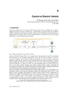
7 6 Eq. 6 describes a traveling wave which moves around the stator at a velocity As long as the applied frequency is constant, Eq. 7 tells us that the speed of a Synchronous motor will be constant. Therefore, the only way to change the speed of a Synchronous motor is to change the applied frequency. However, if the frequency is decreased to slow the motor and the field current is held constant, the back EMF and the Synchronous impedance also decrease. Thus, if the applied voltage Vt is held constant, the armature current will increase until it burns the Synchronous Machines Revised: October 4, 2021 5 of 23 armature windings.
8 Therefore, to control the speed of a Synchronous motor, the terminal voltage must be adjusted roughly proportionally to the frequency. PfNsync120 RPM Eq. 7 where Nsync = Synchronous speed f = applied frequency, Hz P = number of magnetic poles in machine Figure 3 and 4 illustrate the concept of the rotating MMF. Figure 3: Balanced three-phase alternating currents showing time increments. Synchronous Machines Revised: October 4, 2021 6 of 23 Figure 4: Representation of the rotating magnetic field for three time increments from Figure 3. Having previously established the rotor magnetic field and having now established the stator magnetic field, the machine will attempt to align the two fields.
9 This attempt at alignment produces torque at the rotor shaft. However, since the stator field is rotating at Synchronous speed, the rotor is dragged right along with the stator field, thus producing a continuous torque. The two fields can only completely align themselves if there is no load torque attempting to turn the rotor in the opposite direction. If a load torque exists, the fields must separate enough to produce the required torque. The concept is described by Eq. 8 and illustrated by Figure 5. Synchronous Machines Revised: October 4, 2021 7 of 23 Figure 5: An elementary cylindrical rotor Synchronous machine.
10 From Reference 1, the torque produced by the cylindrical rotor machine is FFPuTRsodevgD2 sin Eq. 8 where Tdev developed torque P = number of poles D = rotor diameter = length of rotor (axial) g = length of gap Synchronous Machines Revised: October 4, 2021 8 of 23 Eq. 8 indicates that the torque is proportional to the peak values of the stator and rotor MMF s and the sine of the electrical space angle between them. The negative sign indicates that the fields are attempting to align themselves. Of course, an equal and opposite torque is established within the stator.