Transcription of SYSTEM-10 BTU METER Installation and Operation Guide
1 SYSTEM-10 BTU METER . Installation and Operation Guide For Software Version DM and Higher 11451 Belcher Road South, Largo, FL 33773 USA Tel +1 (727) 447-6140 Fax +1 (727) 442-5699. 0651-23 / 18323 03-18. SAFETY INFORMATION. This METER was calibrated at the factory before shipment. To ensure correct use of the METER , please read this manual thoroughly. Regarding this Manual: This manual should be passed on to the end user. Before use, read this manual thoroughly to comprehend its contents. The contents of this manual may be changed without prior notice. All rights reserved. No part of this manual may be reproduced in any form without ONICON's written permission. ONICON makes no warranty of any kind with regard to this material, including, but not limited to, implied warranties of merchantability and suitability for a particular purpose. All reasonable effort has been made to ensure the accuracy of the contents of this manual.
2 However, if any errors are found, please inform ONICON. ONICON assumes no responsibilities for this product except as stated in the warranty. If the customer or any third party is harmed by the use of this product, ONICON assumes no responsibility for any such harm owing to any defects in the product which were not predictable, or for any indirect damages. Safety Precautions: The following general safety precautions must be observed during all phases of Installation , Operation , service, and repair of this product. Failure to comply with these precautions or with specific WARNINGS given elsewhere in this manual violates safety standards of design, manufacture, and intended use of the product. ONICON Incorporated assumes no liability for the customer's failure to comply with these requirements. If this product is used in a manner not specified in this manual, the protection provided by this product may be impaired.
3 The following symbols are used in this manual: WARNING. ! Messages identified as Warning contain information regarding the personal safety of individuals involved in the Installation , Operation or service of this product. CAUTION. ! Messages identified as Caution contain information regarding potential damage to the product or other ancillary products. i IMPORTANT NOTE. Messages identified as Important Note contain information critical to the proper Operation of the product. 11451 Belcher Road South, Largo, FL 33773 USA Tel +1 (727) 447-6140 Fax +1 (727) 442-5699 SYSTEM-10 BTU METER Manual 09/18 - 0651-24 / 18323 Page 2. TABLE OF CONTENTS. INTRODUCTION .. 5. PURPOSE OF THIS 5. TYPICAL SYSTEM-10 BTU METER .. 5. STANDARD FEATURES AND 5. ADDITIONAL REQUIRED HARDWARE .. 7. WORKING ENVIRONMENT .. 7. SERIAL NUMBER .. 7. UNPACKING .. 8. CHECKING THAT YOU HAVE RECEIVED 8. 9. SITE SELECTION .. 9. MECHANICAL Installation .
4 10. Main Unit 10. Thermowell Installation .. 11. Standard 11. Hot Tap 11. Temperature Sensor Installation .. 13. Flow METER 14. ELECTRICAL Installation .. 15. Input 15. Input Signal 18. Input Signal Connections from Temperature Sensors .. 18. Input Signal Connections from Insertion Turbine Meters. 19. Input Signal Connections from F-2500 19. Input Signal Connections from F-2600 & F-2700 20. Input Signal Connections from F-3100 & F-3200 20. Input Signal Connections from F-3500 21. Input Signal Connections from FB-3500 21. Input Signal Connections from F-4200 22 Input Signal Connections from F-4600 23 Contact Closure Input for Flow 24. Contact Closure Output for Energy Total(s) and 24. Isolated Analog Output(s) (Optional) .. 25. SYSTEM-10 START-UP AND COMMISSIONING .. 26. DISPLAY AND KEYPAD 26. PROCESSOR START-UP .. 26. UNITS AND 27. ANALOG 27. ENABLING / DISABLING FRONT PANEL 28. 29. 11451 Belcher Road South, Largo, FL 33773 USA Tel +1 (727) 447-6140 Fax +1 (727) 442-5699 SYSTEM-10 BTU METER Manual 09/18 - 0651-24 / 18323 Page 3.
5 TABLE OF CONTENTS (CONTINUED). 32. 32. Diagnostic 32. Flow Test 32. Temperature Test 33. ALARM STATUS MENU 33. TROUBLESHOOTING Guide FOR ONICON SYSTEM-10 BTU. MEASUREMENT 34. APPENDIX A DRAWINGS. A-1 TYPICAL SYSTEM-10 Installation . A-2 STANDARD THERMOWELL ASSEMBLY. A-3 THERMOWELL Installation . A-4/A-5 HOT TAP THERMOWELL (2 Pages). A-6 OUTDOOR THERMOWELL ASSEMBLY. A-7/A-8 HEAVY DUTY THERMOWELL FOR HIGH TEMPERATURE / PRESSURE (2 Pages). A-9 TEMPERATURE SENSOR ASSEMBLY. A-10 MOTHER BOARD TEMPERATURE SENSOR INPUT CONNECTIONS. A-11 MOTHER BOARD INSERTION TURBINE METER INPUT CONNECTIONS. A-12 MOTHER BOARD F-2500 VORTEX METER INPUT CONNECTIONS. A-13 MOTHER BOARD F-2600 & F-2700 VORTEX METER INPUT CONNECTIONS. A-14 MOTHER BOARD F-3100 & F-3200 ELECTROMAGNETIC INPUT CONNECTIONS. A-15 MOTHER BOARD F-3500 ELECTROMAGNETIC INPUT CONNECTIONS. A-16 MOTHER BOARD FB-3500 ELECTROMAGNETIC INPUT CONNECTIONS. A-17 SYSTEM-10 TO F-4200 FLOW METER INPUT CONNECTIONS.
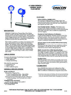
6 A-18 MOTHER BOARD. A-19 BTU COMPUTER BOARD. A-20 POWER SUPPLY BOARD. A-21 BTU METER ANALOG OUTPUT BOARD (with 1 analog output). A-22 BTU METER ANALOG OUTPUTS BOARD (with 4 analog outputs). 11451 Belcher Road South, Largo, FL 33773 USA Tel +1 (727) 447-6140 Fax +1 (727) 442-5699 SYSTEM-10 BTU METER Manual 09/18 - 0651-24 / 18323 Page 4. SECTION : INTRODUCTION. PURPOSE OF THIS Guide . The purpose of this Guide is to provide Installation and commissioning procedures and basic operating and servicing instructions for the ONICON SYSTEM-10 BTU METER . WARNING. ! Only qualified service personnel should attempt to install or service this product. Serious injury may result from the improper Installation or use of this product. TYPICAL SYSTEM-10 BTU METER . ONICON'S SYSTEM-10 is a true heat (Btu) computer, which accepts data from several sensors, performs a series of computations with that data, and displays and/or transmits the results as an indication of the amount of heat (Btu's) being transferred per unit time or as a totalized amount.
7 ONICON Insertion Flow METER BTU X 10,000. 24 VAC Input SCROLL RESET PROGRAM. Signal Connections to Control System SYSTEM-10 . BTU METER . Supply Temp Sensor Heat Exchanger Supply Return Temp Sensor Return STANDARD FEATURES AND SPECIFICATIONS. Single mode Btu calculations, in either the heating or cooling mode, are totalized, and displayed. Two-pipe dual mode Btu calculations in both the heating mode and the cooling modes, are totalized and displayed. Bi-directional dual mode Btu calculations are totalized and displayed. 11451 Belcher Road South, Largo, FL 33773 USA Tel +1 (727) 447-6140 Fax +1 (727) 442-5699 SYSTEM-10 BTU METER Manual 09/18 - 0651-24 / 18323 Page 5. GENERAL SPECIFICATIONS. CALIBRATION LIQUID FLOW SIGNAL INPUT. Flow METER and temperature sensors are individually Standard: 0-15 V pulse output from any ONICON flow METER calibrated, followed by a complete system calibration. Optional: 4 - 20 mA analog output from any flow METER Field commissioning is also available.
8 TEMPERATURE RANGE. Liquid temperature range: 25 to 200 F. ACCURACY Ambient temperature range: -20 to 140 F. TEMPERATURE. MAINTENANCE. Overall differential temperature measurement uncertainty of ONICON recommends periodic inspection and recalibration F over the stated range for sensors connected to the SYSTEM-10 BTU METER . No other (Includes uncertainty associated with the sensors, periodic maintenance is required for the main unit. transmitters, cabling and calculator input circuitry). MECHANICAL. Temperature sensors meet EN1434 / CSA accuracy ELECTRONICS ENCLOSURE: requirements for 1K sensors for cooling applications, 32 77 F. Standard: Steel NEMA 13, wall mount, 8 x 10 x 4 . Temperature sensors meet EN1434 / accuracy TEMPERATURE THERMOWELLS: requirements for 2K sensors for heating applications, 140 212 F. Standard: NPT brass thermowells (length varies with CALCULATOR pipe size) with junction box Computing nonlinearity within Note: 6 pipes and larger require SS thermowell option Optional: Calculator meets EN1434 / class 1 accuracy NPT stainless steel thermowells requirements for 2K sensors for all applications Outdoor junction box with thermal isolation Hot tap thermowells for installations in a TEMPERATURE SENSORS.
9 Pressurized system with no shutdown Solid-state sensors are custom calibrated using traceable temperature standards. ELECTRICAL. Current based signal (mA) is unaffected by wire length. PROGRAMMING WARNING. Factory programmed for specific application. MEMORY. ! All electrical connections must be made in accordance with the information provided Nonvolatile EEPROM memory retains all program here. Failure to do so will result in an parameters and totalized values in the event of increased risk of injury. power loss. This equipment is intended for Installation CATEGORY. DISPLAY (OVERVOLTAGE CATEGORY) II applications. Alphanumeric LCD displays total energy, total flow, INPUT POWER: energy rate, flow rate, supply temperature, return Factory Selectable: temperature. serial number and alarm status 24 VAC: 20 - 28V, 50/60 Hz, 500 mA. Alpha: 16 character, high 120 VAC: 108 - 132V, 50/60 Hz, 250 mA. Numeric: 8 digit, high 240 VAC: 207 - 253V, 50 Hz, 250 mA.
10 Rate Display Range: 0 - 9,999,999 INTERNAL FUSE RATING: Total Display Range: 0 - 9,999,999 24 VAC - 1 Amp Slo-Blo, 3AG Fuse The totals will roll over to zero when the maximum 120 VAC - 1/4 Amp Slo-Blo, 3AG Fuse count is exceeded. 240 VAC - 1/8 Amp Slo-Blo, 3AG Fuse OUTPUT SIGNALS OUTPUT: Standard: Isolated solid-state dry contacts for energy total 24 VDC, 250 mA maximum Maximum contact ratings: 100 mA, 50 VDC OVERCURRENT PROTECTIVE DEVICE RATINGS: Contact duration: , 1, 2 or 6 seconds (factory selectable) Supply mains overcurrent protective devices with the Optional: Multiple isolated analog outputs for energy rate, following ratings: flow rate, supply and return temperature and delta 120 VAC 50/60 Hz 15 A. temperature (factory selectable) 240 VAC 50 Hz 6 A. Output type: 4-20 mA, 0-10 V or 0-5 V (field selectable) WIRING: Optional Interval Data Logging: This option Temperature signals: Use 18-22 ga twisted shielded pair provides up to 24 hours of rate and total data Flow signals: Use 18-22 ga shielded cable see flow logging in 15 minute intervals.