Transcription of Wavetronix SmartSensor HD Installation Guide - Signal …
1 SmartSensor 125 user Guide Wavetronix LLC 4/26/07 SmartSensor 125 Installation Guide Wavetronix LLC 380 S. Technology Ct. Lindon, Utah 84042 USA Voice: (801) 764-0277 Fax: (801) 764-0208 Web: E-mail: 2007 Wavetronix LLC. All Rights Reserved. SmartSensor HD, SmartSensor Manager HD, Click!, Wavetronix , and all associated logos are trademarks of Wavetronix LLC. All other product or brand names as they appear are trademarks or registered trademarks of their respective holders. Protected by Patent Nos. 6,556,916 and 6,693,557. Other and international patents pending. The Company shall not be liable for any errors contained herein or for any damages arising out of or related to this document or the information contained therein, even if the Company has been advised of the possibility of such damages.
2 This document is intended for informational and instructional purposes only. The Company reserves the right to make changes in the specifications and other information contained in this document without prior notification. SmartSensor 125 user Guide Wavetronix LLC 4/26/07 2 Contents Product Symbol Introduction ..5 Unpacking the Installing the SmartSensor 1. Applying Silicon Dielectric 6 2. Attaching SmartSensor HD to the Mounting Bracket .. 6 3. Mounting SmartSensor HD to a 7 4. Connecting the SmartSensor Cable .. 10 5. Connecting the SmartSensor HD to Power and Communication Devices .. 11 6. Configuring SmartSensor HD Using SmartSensor Manager HD.
3 16 Automatic Configuration .. 23 Manual Configuration .. 25 Appendix A SmartSensor HD Specifications ..30 Appendix B Communications Connector Pin Outs ..31 Appendix C Old Cable Connector Appendix C-1 Click! 200/204 Appendix C-2 SmartSensor Cable Pin Socket Assignments ..35 Appendix C-3 PC and Modem Appendix D Cable Lengths ..38 SmartSensor 125 user Guide Wavetronix LLC 4/26/07 3 Product Notifications FCC Part 15 Compliance This equipment complies with Part 15 of the Federal Communications Commission (FCC) rules. Any changes or modifications not expressly approved by the manufacturer could void the user s authority to operate the equipment.
4 NOTE: This equipment has been tested and found to comply with the limits for a Class A digital device, pursuant to part 15 of the FCC Rules. These limits are designed to provide reasonable protection against harmful interference when the equipment is operated in a commercial environment. This equipment generates, uses, and can radiate radio frequency energy and, if not installed and used in accordance with the instruction manual, may cause harmful interference to radio communications. Operation of this equipment in a residential area is likely to cause harmful interference, in which case the user will be required to correct the interference at his or her own expense.
5 Risk of Electrical Shock An authorized electrical technician should perform Installation and operation of this unit. Persons other than authorized and approved electrical technicians should NOT attempt to connect this unit to a power supply and/or traffic control cabinet, as there is a serious risk of electrical shock through unsafe handling of the power source. Extreme caution should be used when connecting this unit to an active power supply. Technical Service Do not attempt to service or repair this unit. This unit does not contain any components and/or parts serviceable in the field. Any attempt to open this unit, except as expressly written and directed by Wavetronix , will void the customer Warranty.
6 Any visible damage to exterior seal labels will void the Warranty. Wavetronix is not liable for any bodily harm or damage caused if unqualified persons attempt service or open the back cover of this unit. Refer all service questions to Wavetronix or an authorized distributor. Installation Safety Precaution Caution should be used when installing any sensor on or around active roadways. Serious injury can result when Installation is performed using methods that are not in accordance with authorized local safety policy and procedures. Always maintain an appropriate awareness of the traffic conditions and safety procedures as they relate to specific locations and installations.
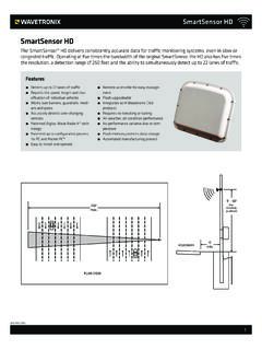
7 SmartSensor 125 user Guide Wavetronix LLC 4/26/07 4 Symbol Legend The lightning bolt within an equilateral triangle symbol is intended to alert the user to the risk of electric shock. The exclamation point within an equilateral triangle is intended to alert the user to the presence of important Installation , operating, and maintenance instructions. SmartSensor 125 user Guide Wavetronix LLC 4/26/07 5 Introduction The Wavetronix SmartSensor HD traffic sensor utilizes the latest technology to collect and deliver traffic statistics. The SmartSensor HD collects information through the use of a GHz (K band) operating radio frequency and is capable of measuring traffic volume, average speed, individual vehicle speed, lane occupancy, and presence.
8 Classified as Frequency Modulated Continuous Wave (FMCW) radar, the SmartSensor HD detects and reports traffic conditions simultaneously over as many as ten lanes of traffic. Once SmartSensor HD is installed, the configuration process is quick and easy. After Installation , this unit will require little or no on-site maintenance and can be remotely reconfigured for optimal performance. This Installation Guide provides the step-by-step process of installing and configuring the SmartSensor HD. Any questions about the information in this Guide should be directed to Wavetronix or your distributor. Unpacking the Sensor A typical sensor package contains the following items: SmartSensor HD SS125 detector with installed back-plate Sensor mount bracket and nuts Sensor cable SmartSensor HD Installation Guide CD and/or diskette with software If any of these items are missing, note the serial number located on the side of the sensor and contact Wavetronix support.
9 Additional products may be purchased through your distributor; software and firmware may be obtained through Wavetronix Sales. The following optional items are not included unless specifically ordered (check packing list for actual inventory): Click! 172/174 contact closure adapter Click! 200 surge protector Click! 201 1 Amp AC to DC converter Click! 202 2 Amp AC to DC converter Click! 300 RS-232 to RS-485 adapter Click! 301 Ethernet to Serial adapter Click! 400 900 MHz Spread Spectrum Radio Click! 401 Serial to Converter Click! 403 Bluetooth to Serial Converter Click! 700 Serial to Fiber Optic Converter SmartSensor 125 user Guide Wavetronix LLC 4/26/07 6 Installing the SmartSensor HD The SmartSensor HD Installation process involves the following six steps: 1.
10 Applying silicon dielectric compound 2. Attaching the SmartSensor HD to the mounting bracket 3. Mounting the SmartSensor HD to a pole 4. Connecting the SmartSensor cable 5. Connecting the SmartSensor HD to Power and Communication Devices 6. Configuring the SmartSensor HD using SmartSensor Manager HD Each step is described in detail in this section. 1. Applying Silicon Dielectric Compound Use the following steps to correctly apply the silicon dielectric compound: 1. Take the tube of Silicon Dielectric Compound and tear off the tab. 2. Squeeze about 25% of the silicon into the connector at the base of the SmartSensor HD (see Figure 1). Be sure to wipe off any excess compound.