Transcription of SYSTEM 2100 - compu-aire.com
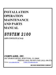
1 INSTALLATION OPERATION MAINTENANCE AND PARTS MANUAL S Y S T E M 2 1 0 0 AIR COOLED (CAA) COMPU- aire , INC. 8167 BYRON ROAD, WHITTER,, CA 90606 PHONE: (562) 945-8971 FAX: (562) 696-0724 Website: E-mail: ISO 9002 REGISTERED COMPANY . I N DE X DESCRIPTION PAGES 1. INTRODUCTION, PRE-INSPECTION AND UNCRATING 1 - 5 2. TECHNICAL AND ELECTRICAL DATA 6 - 7 3. UNIT DIMENSIONS 8 - 9 4. SETTING THE AIR COOLED CONDENSER 10 - 14 5. PIPING CONNECTIONS 15 - 16 6. HUMIDIFIER PIPING CONNECTIONS 17 - 18 7. EVACUATION AND CHARGING PROCEDURES 18 - 21 8. HUMIDIFIER 22 9. ELECTRICAL CONNECTIONS 23 - 24 10. WIRING 25 - 29 START-UP AND TEST PROCEDURE 30 - 33 12. SYSTEM 2200 PROGRAMMABLE CONTROLLER 34 13. SERVICE AND MAINTENANCE INSTRUCTIONS 35 - 44 14. TROUBLE-SHOOTING (HUMIDIFIER) 45 - 48 15. PARTS 49 - 56 16. WARRANTY AND WARRANTY CERTIFICATE 57 - 59 F:\WP\MANUALS\ ADDENDUM CORRECT PHASING OF SCROLL COMPRESSORS: The scroll compressor is a unidirectional compressor and will only compress refrigerant in one rotation direction.
2 Therefore, the proper rotation of the scroll compressor must be checked. The scroll compressor will run in the reverse direction but it will not pump refrigerant and will draw substantially reduced current as compared to listed values, and will result in elevated sound levels. Scroll compressor will trip on internal protection after running for some time in the reverse direction. Verification of the proper rotation of the scroll compressor is done by observing that suction pressure drops and discharge pressure rises when the compressor is energized. WARNING: EXTENDED IMPROPER ROTATION OPERATION MAY ALSO VOID COMPRESSOR WARRANTY. Contacting Compu- aire for Technical Assistance Compu- aire , Inc. uses the latest in electronic and software technologies to develop some of the most reliable and cost efficient air conditioning systems in the world. Since many of our customer installations are sensitive to down time, we stock nearly all components for your SYSTEM ready for same day shipment.
3 In addition, our service departments can usually diagnose and repair the electronic components and return them to you within a few days. Our customer support staff is available should you require assistance in diagnosing a problem or in setting up your air conditioning SYSTEM . During usual business hours, you may call at (310) 945-8971 between 7:00 AM and 3:30 PM Pacific time, Monday through Friday except holidays. Or, you may send a facsimile message at (310) 696-0724 anytime_ Finally, you may write us at Compu- aire , Inc., 8167 Byron Road, Whittier, California 90606. Please, do not return SYSTEM components without prior authorization from Compu- aire . Whether repairing or replacement is required for in warranty or out of warranty parts, Compu- aire must know what is being returned and why so that we may keep proper records of your parts. Call Compu- aire 's service center for a returned materials authorization number (RMA) and clearly mark all packages on the outside with the number before sending them to us.
4 When contacting the factory, please have information ready as to the model and size of the air conditioner SYSTEM and most important, the job number. Compu- aire keeps a file on each machine sold detailing SYSTEM components using this latter number. All such information can be found on the Warranty Plate attached to each machine. I. CONTROL MONITOR 6 BLOWER II. COMPRESSOR IS_ POWER PANEL 2, CONTACTOR 7. FILTER RACK 12. S I G H T G L A S S 17. PRESSURE SWITCH 3. REHEAT ASSEMBLY 6 NORTEC HUMIDIFIER 13. E X PANSION VAL VE 18 RECEIVERS. 4 COOLING COIL 9 SOLENOID VALVE 14 DISCONNECT SWITCH 19. SUCTION ACCUMULATORS Z. BLOWER MOTOR 10. DRIER 15. FUSE BLOCK 20. CLOGGED FILTER SWITCH 21. NO AIR FLOW SWITCH 22. N A M E P L A T E INTRODUCTION Compu- aire SYSTEM 2100 is specially designed to simultaneously cool, heat, humidify, de-humidify and filter the computer room air. These units are typically down discharge type supplying air in the computer raised floor.
5 Standard Air Cooled SYSTEM 2100 Units are equipped with: 1) The Base Unit with dual refrigeration SYSTEM . 2) Matching Air Cooled Condenser 3) Low Ambient Control-Variable Speed Type 4) Control Panel for the Air Cooled Condenser Features of SYSTEM 2100 Air Conditioner include: 1) Stainless Steel Condensate Pan 2) Hermetic Compressors 3) Disposable Generator Type Humidifier 4) Disposable 2" filters 5) Microprocessor Based Control Monitor 6) Dual Belts Drive Set with an adjustable Motor pulley 7) Draw Thru Air Flow OPTIONAL ITEMS WHEN ORDERED 1) Semi Hermetic Compressors 2) Up Flow Discharge 3) Mounting Stand 4) Hot Water, Steam, or hot Gas Reheat 5) Steam, Electric Immersion, or Infra Red Humidifier 6) Electromechanical Control Panel 7) Remote Control Panel 8) 4" Filters 9) 1" Pre-filters 10) F i r e s t a t 11) Smoke Detector 12) Molded Case Disconnect Switch 13) Condensate Pump 14) Low Ambient Control Below -20 F 15) Condensate Overflow 16) Low Voltage Drop Out PRELIMINARY SURVEY Prior to installing the unit verify the following requirements.
6 1) Door Openings 2) Elevator Size if needed to be used. 3) Electrical a) Voltage and Phase b) Amps c) Breaker Size 4) Floor Openings 5) Water Supply for the Humidifier 6) Condensate Drain Connection Point 7) Refrigerant Pipe Routing make sure it does not interfere with air flow. 8) Air Cooled Condenser a) Verify Electrical Service b) Location and Structural Integrity c) Space allocation for running 2 Liquid Lines and 2 Hot Gas Lines d) Flashing Requirements e) Space to Run Electrical Conduit for Interlocking conductors from the unit to the Air Cooled Condenser. PRE-INSPECTION Upon receipt of the units, inspect the items for either visible or concealed damage. REPORT ANY DAMAGE TO THE CARRIER. COMPU- aire IS NOT RESPONSIBLE FOR FILING OF ANY CLAIMS. ALL NEEDED INSPECTION AND CLAIM FILING IS THE RESPONSIBILITY OF THE RECEIVER. LOCATING THE AIR CONDITIONER Proper clearance is important for the unit function and access to various components for adjustment and repair or replacement.
7 Front* 36" Left Side 36" Right Side 36" *Consult Electrical Codes and provide clearance UNCRATING The units are shipped as follows: 1) SYSTEM 2100 - wrapped with cardboard and wooden crated. 2) Air Cooled Condenser - wooden crated 3) Control Panel - corrugated box and shipped separately. 4) Optional items when ordered such as remote control panel, water detectors, floor stands, etc. are shipped separately in its own box. Extreme care should be exercised in handling these units. SYSTEM 2100 unit is specifically painted to match or contrast the computer equipment. Exercise care when removing the covers. Make sure the forks are under the entire unit and protruding on the far side prior to lifting. SETTING THE UNIT If the raised floor is already installed use RUBBER TIRE DOLLIES to move unit to its location. If the floor is not installed Mounting Stand may be used to install the unit. An alternate method of setting the unit is with the use of leveling jack stands.
8 The height of the unit can be raised or lowered through the use of the adjusting rods. The locknuts must be tightened to assure rigidity, as shown below. UPFLOW UNITS - The unit may be placed directly on the sub floor. The upflow unit has an optional 20" high discharge plenum. SETTING THE AIR COOLED CONDENSER Rigging: Move the unit to the installation location using a crane or fork lift. Each fan section has heavy leg supports with lifting holes at the top. Do not lift with a choke sling around the unit. Spreader bars are recommended for lifting multiple fan units. Under no circumstances should the coil headers or piping be used for lifting the unit. Leg Assembly: The legs must be unbolted from the shipping position and extended prior to placing the unit on it's pad. Each leg extends down approximately 18 inches and reattaches using same bolts. LOCATING THE CONDENSER The remote heat exchangers must be located in an area that will ensure free air flow into and out of the unit.
9 The unit should not be placed closer than 36 inches from any wall or other obstruction. When two or more units are used in the same area, space them apart by a minimum of 48 inches. Heat exchanger piping connections: Piping must be supported within 36 inches of the inlet and outlet connections. The inlet connection is located on the top header on all units. The outlet connection is located on the bottom header of all unit. INSTALLING THE CONTROL PANEL Control Panel is shipped separately for field mounting in the control box. The control panel consists of: 1) Power Terminal Block 2) Low Voltage Interlock Terminal Block 3) Contactors 4) Control Transformer 5) Ambient Thermostats Follow the following steps to install this Control Panel inside this Control Box : 1) Remove wires from the terminal block in the Control Box , tag them so they do not get mixed up. 2) Install the control panel with sheet metal screws. 3) Install wires from each conductor as shown on the diagram. 4) Attach the refrigerant fitting from the SCR controller to the factory installed schraeder fitting on the liquid lines.
10 Exercise extreme care so the capillary line is not kinked. 5) Install the bulb(s) of the ambient stats on the side of the Air Cooled Condenser. Make sure to shield this bulb from direct sun light. Standard Air cooled condenser is provided with Fan Speed control type low ambient control FAN SPEED CONTROL Fan speed control provides an infinite number of speed variations on specially designed permanent split-capacitor motors. Control varies the quantity of passing air through the air cooled condenser by directly sensing the refrigerant head pressure. OPERATION Fan Speed Control provides air delivery in direct proportion to heat rejection requirements of the SYSTEM . This is to maintain optimum SYSTEM capacities and pressures in widely varying operating ambient. As the ambient temperature drops, the head pressure will also drop. As the head pressure drops, this will sensed by the pressure transducer and the air quantity will be reduced thereby raising the head pressure and maintaining the fixed condensing point.