Transcription of System 350 Display Modules - grainger.com
1 System 350 Product guide 930 Add-On Modules SectionProduct/ technical Bulletin D350 Issue Date 0200 2000 Johnson Controls, No. 24-7664-206, Rev. No. LIT-930070 System 350 Display ModulesThe D350, D351, and D352 Display Modules aredesigned for use with System 350TM temperature,humidity, and pressure controls to provide a digitalreadout of sensor or setpoint values at the push of are all System 350 products, the Display modulesare housed in a NEMA 1 high-impact thermoplasticenclosure. The modular design provides easy,plug-together connections for quick installation andfuture 1: System 350 Display Module Features and Benefits Modular DesignEnables control , stage, and Display modulesto be purchased and installed as necessary Plug-together Connectorsand 35 mm DIN RailMountingEliminates wiring between Modules andreduces installation costs Various Models DisplayTemperatures ( F and C),Humidity Levels(0 to 100%), orPressures (in psi or in.)
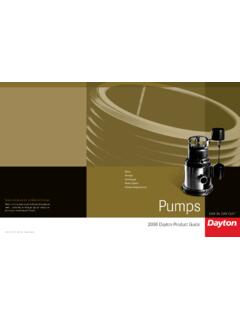
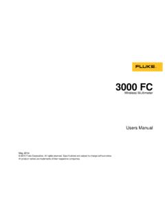
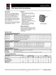
2 Provides visual sensor and setpoint indicationfor System 350 controls Continuous Readout ofSensor Value; Front AccessButton Can Be Pushed toDisplay SetpointPermits use as a monitoring device and/or asetup tool Can be Remote MountedUsing WHA29A CableAssembliesExtends monitoring capabilities up to 50 ft( m)2 Add-On Modules System 350 Display Modules Product/ technical BulletinApplication OverviewSystem 350 Display Modules can be permanentlyinstalled in a System 350 control System or used forremote setup or adjustments to the System can be made accuratelyby using the Display Modules during setup. Forapplications where a Display module will not bepermanently mounted, the service technician can usean optional extension cable (WHA29A-600R) totemporarily connect a Display module to the System toverify the sensor reading and FOR SETPOINTD3503-DigitLCD DisplayModuleConnectorSetpointButtonModu leConnectorFigure 2: Display Module FeaturesOperationThe Display Modules receive their power, sensor, andsetpoint information from a System 350 controlmodule.
3 A 3-digit LCD (Liquid Crystal Display ) providescontinuous readout of the sensor view the setpoint reading, press the PRESS FORSETPOINT button located on the face of the button must be pressed and held forapproximately three :The D350, D351, and D352 Display Modules are matched tothe A350, W351, and P352controls, respectively. If anincorrect Display module is usedon a System , the Display providesinaccurate readings. See Table 2for more information on choosingthe correct D350 Display !WARNING:Risk of Electrical power supply beforemaking electrical connections toavoid possible electrical shock orequipment Display Modules are housed in a compact NEMA 1plastic enclosure designed for standard 35 mm DIN railmounting. The Modules are not position sensitive, butthey should be mounted for convenient wiring andadjustment. Four key-slot mounting holes on the backof the control case are provided for surface mountingwhen Display Modules plug into the control and otherSystem 350 add-on Modules via 5-pin connectorslocated on either side of each 350 Modules can be arranged in any order;external wiring is not required to interconnectcomponents.
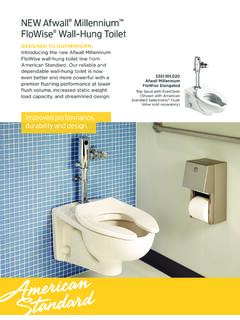
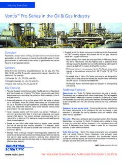
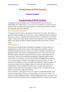
4 (For optimal System accuracy, mount theD350 series Modules at the far right end of thesystem.) The System becomes operational as soon aspower is wire cable assemblies in various lengths areavailable for remote mount applications. See Table RailMountsPRESS FOR SETPOINT3/16 (4)Mounting Slotsfor No. 6 Screws1/2 (13)2-15/16(75)7/16 (11)1-9/16(40)5 (127)2-3/8 (61)1-3/16 (31)ConduitHole7/8 (22)7/8 (22)2-3/8(61)Figure 3: Module Dimensions, in. (mm) Add-On Modules System 350 Display Modules Product/ technical Bulletin 3 Checkout ProcedureBefore applying power, make certain that theinstallation and wiring connections are according to jobspecifications. After necessary adjustments andelectrical connections have been made, put the systeminto operation and observe at least three completeoperating cycles before leaving the troubleshooting the Display module, verify thatthe System control is functioning properly.
5 Consult theappropriate System 350 bulletin for operatingspecifications and troubleshooting the control is functioning properly, use the followingprocedure to troubleshoot the Display Measure the temperature, pressure, or humiditywith an instrument that is at least as accurate asthe sensor in the System , and compare this withthe readout on the Display If these values do not match within areasonable range (for example, ), checkthe sensor for proper wiring and to the appropriate sensor bulletin forinformation on sensor If the sensor is wired and operating correctlyand the Display reading is incorrect, the displaymodule must be Press the PRESS FOR SETPOINT button on thefront of the Display module. If the value displayedon the LCD is out of range, replace the displaymodule. Refer to Table 1 for out-of-range valuesfor the various Display If pressing the PRESS FOR SETPOINT buttonresults in a reading other than the expectedsetpoint value, check the setpoint dial setting andcorrect if necessary.
6 If the Display continues toread an incorrect value, replace the 1: Out-of-Range ValuesDisplayModuleModelOut-of-RangeSetp oint ValueOut-of-RangeSensor ValueD350AA-1 Greater than260 F or 130 CGreater than 300 F or150 CD351AA-1 Greater than95% RHGreater than100% RHD352AA-2 Greater than700 psiGreater than 750 psiD352CA-1 Greater in. in. in. 2: Controls and Related DisplayModulesControl ModuleModelsDisplay ModuleModelsA350A/B, A350E, A350P,A350R, A350SD350W351, W351PD351P352AB-2, P352AB-3,P352AB-4, P352PN-2,P352PN-3, P352PN-4D352AA-2P352PQ-1D352CA-1P352PQ-2 D352CA-2 Repairs and ReplacementField repairs or calibration must not be replacement Modules , contact the nearestJohnson Controls Add-On Modules System 350 Display Modules Product/ technical BulletinOrdering InformationTable 3: Ordering InformationProduct Code NumberDescriptionD350AA-1 CTemperature Display Module with Fahrenheit ScaleD350BA-1 CTemperature Display Module with Celsius ScaleD351AA-1 CHumidity Display Module with Percent RH ScaleD352AA-2C(Not interchangeable with D352AA-1C)Pressure Display Module with 0 to 750 psi ScaleD352CA-1 CPressure Display Module with 0 to in.
7 ScaleD352CA-2 CPressure Display Module with 0 to in. ScaleWHA29A-600R3 ft ( m) Cable, 5-wireWHA29A-603R25 ft ( m) Cable, 3-wire; Requires Y350R at D350 LocationWHA29A-604R50 ft ( m) Cable, 3-wire; Requires Y350R at D350 LocationSpecificationsProductSystem 350 Display ModulesReadout3-digit LCD Continuous DisplaySupply VoltageD350 Provided by the A350 Temperature control ModuleD351 Provided by the W351 Humidity control ModuleD352AA-1;D352AA-2;D352CA-1;D352CA- 2:Provided by the P352 Pressure control ModuleCurrent Draw4 mA (typical)MountingSurface or DIN RailAmbient TemperatureOperating: -30 to 150 F (-34 to 66 C)Shipping:-40 to 167 F (-40 to 75 C)Ambient Humidity0 to 95% RH non-condensingMaterialCase, Cover: NEMA 1 High-impact ThermoplasticAgency ListingsUL CNN XAPXUL Listed for Canada, CNN XAPX7, File E27734 (all models)The performance specifications are nominal and conform to acceptable industry standards.
8 For application at conditions beyond thesespecifications, consult Johnson Controls/PENN Application Engineering at (414) 274-5535. Johnson Controls, Inc. shall not be liable fordamages resulting from misapplication or misuse of its products or misuse of its GroupFAN 930507 E. Michigan StreetSystem 350 Product Box 423 Printed in , WI