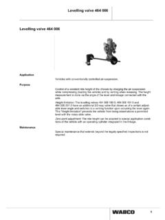
Transcription of Systems And Components In Commercial Vehicles …
1 Systems And Components In Commercial Vehicles2. Edition Copyright WABCO 2005 vehicle Control SystemsAn American Standard CompanyThe right of amendment is reservedVersion 002 (en)8150100033815 010 003 331 PageOperation of Air Braking 41. Motor VehiclesBraking system .. 6 Components of the Motor vehicle s Braking 72. TrailersBraking system .. 64 Equipment For Trailer Braking Systems .. Braking system (ABS) .. Braking Systems On Motor 955. EBS - Elektronisch geregeltes Suspension Systems and ECAS (Electronically Controlled Air Suspension).. Braking Systems In Agricultural and MTS - Elektronic Door Control Systems For Motor 13710. Installation Of Pipes And Screw 15111. 163 Table of Contents4 Operation of Air Braking Systems1.
2 Compressed Air SupplyThe compressed air supplied by the com-pressor (1) flows to the air dryer (3) viathe unloader (2) which automatically con-trols the pressure within the system with-in a range of between and bar, forinstance. In the air dryer , the water va-pour in the air is extracted and expelledthrough the air dryer s vent. The dried airthen flows to the quadruple-circuit pro-tection valve (4) which, if one or severalcircuits are defective, secures the intactcircuits against any loss in the service braking circuits I andII, the air supply from the reservoirs (6and 7) flows to the brake valve (15). InCircuit III the air supply from the reservoir(5) flows through the 2/2-way valve whichis integrated in the trailer control valve(17) to the automatic hose coupling (11)and on to the check valve (13), the handbrake valve (16) and the relay valve (20)into the spring-loaded portion of the Tris-top spring brake actuators (19).
3 Circuit IVsupplies air to any ancillary consumers,in this case an exhaust trailer s braking system receivescompressed air through the hose cou-pling (11) with its supply hose air then passes the line filter (25)and the relay emergency valve (27) be-fore reaching the reservoir (28) and alsoflows to the supply ports of the ABS relayvalves (38).2. Service Braking SystemWhen the brake valve (15) is actuated,compressed air flows via the ABS sole-noid control valve (39) into the brakechambers (14) of the front axle and to theload-sensing valve (18). This valve re-verses and the air flows via the ABS so-lenoid control valve (40) into the servicebrake portion (brake chambers) of theTristop spring brake actuators (19).
4 Thepressure in the brake cylinders generat-ing the force required for the wheel brakedepends on the amount of force appliedto the brake valve, and on the load car-ried on the vehicle . This brake pressureis controlled by the load-sensing valve(18) which is connected to the rear axleby means of a linkage. Any change in thedistance between the vehicle s chassisand its axle caused by loading or unload-ing the vehicle causes the brake pres-sure to be continuously adjusted. At thesame time, via a pilot line, the load-emptyvalve integrated in the brake valve is af-fected by the load-sensing valve. Thusthe brake pressure on the front axle isalso adjusted to the load carried on thevehicle (mostly on lorries).
5 The trailer control valve (17) actuated bythe two service braking circuits pressuriz-es the pilot connection of the relay emer-gency valve (27) after passing the hosecoupling (12) and the connecting con-trol hose. The air supply from the air res-ervoir (28) is thus allowed to passthrough the relay-emergency valve, thetrailer release valve (32), the adaptervalve (33) and on to the load-sensingvalve (34) and the ABS relay valve (37).The relay valve (37) is actuated by theload-sensing valve (34) and the com-pressed air flows to the brake chambers(29) on the front axle. The ABS relayvalves (38) are actuated by the load-sensing valve (35), and the compressedair is allowed to pass to the brake cham-bers (30 and 31).
6 The service pressureon the trailer, which is similar to the out-put pressure from the towing vehicle , isautomatically adjusted by the load-sens-ing valves (34 and 35) for the load carriedon the trailer. In order to prevent overb-raking of the wheel brake on the frontaxle in the partial-braking range, theservice pressure is reduced by the adapt-er valve (33). The ABS relay valves (on5the trailer) and the ABS solenoid controlvalves (on the towing vehicle ) are used tocontrol (pressure increase, pressurehold, pressure release) the brake cylin-ders. If these valves are activated by theABS ECU (36 or 41), this control processis achieved regardless of the pressure al-lowed to pass by the brake valve or therelay emergency they are not needed (solenoids aredead), the valves operate as relay valvesand achieve a faster increase or de-crease of the pressure for the brake Parking Braking SystemWhen the hand brake valve (16) is actu-ated and locked, the spring-loaded por-tions of the Tristop spring brakeactuators (19) are exhausted fully.
7 Theforce needed for the wheel brake is nowprovided by the heavily preloadedsprings of the Tristop spring brake actua-tors. At the same time, the pressure inthe line leading from the hand brakevalve (16) to the trailer control valve (17)is reduced. Braking of the trailer com-mences by the pressure increasing in theconnecting supply hose. Since theguideline of the Council of the EuropeanCommunities (RREG) that a tractor-trail-er combination must be held by the motorvehicle alone, the pressure in the trailer sbraking system can be released by mov-ing the hand brake lever into its control position. This permits the parking brakingsystem to be examined as to whether itfulfills the provisions of the Auxiliary Braking SystemDue to sensitive graduation of the handbrake valve (16) the lorry can be brakedby means of the spring-loaded portionseven if the service braking Systems I andII have failed.
8 The brake force for thewheel brake is produced by the force ofthe preloaded springs of the Tristopspring brake actuators (19) as describedunder Parking Braking system althoughthe spring-loaded portions are not ex-hausted fully but only to the extent re-quired for the braking Automatic Braking of the TrailerIn the event of the connecting supply line breaking, the pressure will drop rap-idly and the relay emergency valve (27)will cause full application of the trailer sbrakes. In the event of the connecting control line breaking, the 2/2-way valveintegrated in the trailer control valve (17)will, when the service braking system isactuated, throttle the passage of the sup-ply line leading to the hose coupling (11)to such an extent that the rupture of thesupply line causes a rapid drop in pres-sure in the supply line and the relayemergency valve (27) causes the trailerto be braked automatically within the le-gally stipulated time of no more than 2seconds.
9 The check valve (13) securesthe parking braking system against anyinadvertent actuation if the pressuredrops in the supply line leading to ABS ComponentsThe motor vehicle usually has three tell-tale lamps (ASR having one additionallamp) fitted for indicating functions andfor continuously monitoring the system . Italso has a relay, an information moduleand an ABS socket (24).After actuating the driving switch, the yel-low telltale lamp will come on if the trailerhas no ABS or if the connection has notbeen established. The red lamp will go offwhen the vehicle exceeds a speed of ap-prox. 7 and the safety circuit of theABS electronics has not detected an of Air Braking Systems6 Air braking system with ABS/ASR (4S/4M)
10 dryer with combined unloader3 Four circuit protection valve4 Air reservoir5 Clamps6 Test coupling7 Drain valve8 Check valve9 Brake valve with integralauto load proportioning valve10 Hand control valve withtrailer control11 Relay valve12 Piston cylinder13 Brake chamber14 ASR-Control cylinder153/2 Solenoid valve16 Tristop-Brake actuator17 Quick release valve18 Load sensing valve19 Knuckle joint20 Trailer control valve21 Hose coupling, supply22 Hose coupling, control23 Two-Way valve24 ABS Warning lamp25 ABS Info lamp26 ABS-socket27 Sensor extension cable28 Solenoid cable29 Socket 30 Sensor braket31 Sensor with cable32 Pole wheel33 ABS-Solenoid valve34 Electronic control unit35 Info module36 Pressure switch37 Proportional valve383/2 Directional control valve12381234,5714379171333282729,3031, Of TheMotor vehicle s Braking System8 Air Intake Air FilterPurpose:To prevent impurities from the air gettinginto the compressor (by using suction fil-ters) or into the vents of compressed airequipment (by using vent filters); theyalso serve to muffle the noise caused bythe intake of air or by blowing it :Moist air filters (for normal operating con-ditions).