Transcription of TASKMASTER INSTALLATION - Industrial Fans & Lights
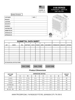
1 ECO 1-7644 REV. 6/20 FORM: 9632 TASKMASTER5100 SERIESH orizontal or Vertical MountingIndustrial / Commercial Unit HeaterNOT FOR RESIDENTIAL USEATTENTION: Read carefully before attempting to install, operate or service the TASKMASTER Unit Heater. Retain these INSTALLATION instructions for future use. PRODUCT FEATURES Forced air electric unit heater available in 208, 240/208, 227, 480, 550 or 600 volt as standard. Ten standard heating capacities of KW/11,260 BTUH thru KW/170, 600 BTUH. 208 and 240/208 volt models are single phase fi eld convertible to three phase on thru KW Models. (Single phase only available on , , and 10 KW 277 volt models. Specially designed inlet louver allows the fan to pull cool air evenly across the high mass all-steel element. Outward drawn venturi and adjustable louver assembly further directs the outlet air in a uniform pattern to meet specifi c air pattern requirements in either the horizontal or vertical mounting position.)
2 Optional wall/ceiling or vertical mounting brackets (as required). Four position weld nuts supplied in case top and back for fi eld mounting by threaded rods or eye bolt with chain. (Hardware supplied by others). Optional radial or anemostat diffusers lending air pattern versatility when mounted vertically. modular control kits for fi eld INSTALLATION . Disconnect switch, thermostat, summer fan switch, heat recovery thermostat. All kits with spade terminals (Except disconnect switch). Single point terminal board wiring of integral control kits. 24 volt low voltage control circuit standard on all contactor and transformer models. Roomy control box with access door locked into position by two (2) 1/4 turn fasteners for ease of INSTRUCTIONS& PARTS LISTIMPORTANT: OWNER SHOULD RETAIN THESE INSTRUCTIONS FOR FUTURE REFERENCE1 ECO 1-7644 REV. 06/20 FORM: 9632 IMPORTANT INSTRUCTIONSWhen using electrical appliances, basic precautions should always be followed to reduce the risk of fi re, electrical shock, and injury to persons, including the following:1.
3 Read all instructions before using this CAUTION: High temperatures. Keep cords and all other combustible material, such as furniture, papers, clothes and curtains away from the heater. For safe and effi cient operation, keep an open space around heater of three feet in front and 12 inches at ends and rear. ATTENTION: Les temp ratures lev es. Gardez les cordons et tout autre mat riau combustible, tels que les meubles, papiers, v tements et rideaux l ext rieur de l appareil de chauffage. Pour un fonctionnement s r et effi cace, garder un espace ouvert autour de chauffage de trois pieds l avant et 12 pouces aux extr mit s et l arri Extreme caution is necessary when any heater is used by or near children or invalids and whenever the heater is left operating and Do not operate any heater after it malfunctions, has been dropped or damaged in any manner. Return heater to authorized service facility for examination, electrical or mechanical adjustment, or Do not use To disconnect heater, turn controls to off, and turn off power to heater circuit at main disconnect panel (or operate internal disconnect switch if provided).
4 7. Do not insert or allow foreign objects to enter any ventilation or exhaust opening as this may cause an electric chock or fi re, or damage the To prevent a possible fi re, do not block air intakes or exhaust in any manner. 9. A heater has hot and arcing or sparking parts inside. WARNING: Do not use it in area where gasoline, paint, or fl ammable liquids are used or Use this heater only as described in this manual. Any other use not recommended by the manufacturer may cause fi re, electric shock, or injury to This heater may include an audible or visual alarm to warn that parts of the heater are getting excessively, hot. If the alarm sounds (or illuminates), immediately turn the heater off and inspect for any objects on or adjacent to the heater that may have blocked the airfl ow or otherwise caused high temperatures to have occurred. DO NOT OPERATE THE HEATER WITH THE ALARM SOUNDING (OR ILLUMINATING)12. SAVE THESE INSTRUCTIONSM aintenance:Caution: Make certain that the power source is disconnected before attempting to service or disassemble any component.
5 If the power disconnect is out of the line of sight, lock it in the OPEN position and tag to prevent the application of power. Make sure the heater has cooled enough to safely :Once a year inspect the control panel wiring to make certain insulation is intact and all connections are tight. Inspect all heater and relay contacts. If the contacts appear badly pitted or burned, replace the :Clean the unit casing, fan and motor once a year. A dirty motor will tend to run hot and eventually will be damage internally. Use the crevice tool on a vacuum cleaner or a clean cloth to clear dust and dirt. Any rust spots on the casing should be cleaned and :All units have fan motors that are permanently lubricated so that only occasional cleaning is 1-7644 REV. 6/20 FORM: 9632 PROPER LOCATION INSTRUCTIONSOnce the total heating load is calculated, the quantity and capacity of the unit heaters must be determined. because a large number of low-capacity heaters provides more uniform heat distribution.
6 This approach is recommended when the area will be occupied by a relatively large number of sedentary personnel, ( working on production lines and at benches.)A large number of smaller capacity unit heaters tends to prevent hot drafts, reduces noise levels, and increases diversity of load to help reduce electrical demand and operating warehouses where even heat distribution and constant temperatures are less important, a smaller number of high capacity units can be used -- in many cases reducing INSTALLATION cost. To maintain reasonable heat distribution and reduce severe stratifi cation even in lower bay areas, the total air volume of the space should pass through the unit heaters about three times per hour. (Take total cubic feet and divide by 20 in order to determine proper total heater CFM rating.)It is important that the rated voltage of the heating equipment match the supply voltage.
7 Supply voltage in excess of the heater rated voltage can damage equipment. Supply voltage lower than the rated heater voltage will decrease heater output as well as run the risk of damaging some unit heaters are recommended in low bay areas with maximum 15 to 18 foot ceilings. These should be concentrated along outside wall or other areas of greatest heat loss; spaced to set up a generally circular air movement, each heater supporting the air stream of the other. Additional vertical down below unit heaters with appropriate accessory diffusers can be located to counteract ceiling heat losses (see Figure 1 Location charts).GENERAL SAFETY INFORMATION / CAUTION:Follow all local electrical and safety codes, as well as the National Electrical Code (NEC) and the Occupational Safety and Health Act (OSHA).To avoid possible electrical shock, be sure the electrical current is turned off at the main switch prior to wiring or servicing of the power disconnect is not integral and is out-of-sight, lock it in the open position and tag to prevent unexpected application of power prior to performing any service or maintenance of the unit when installed must be electrically grounded in accordance with the National Electrical Code and standard industry certain that the power source conforms to the requirements of your equipment.
8 See Table 2 on page 6 for wire and circuit size Check heater voltage and phase on rating label to confi rm that it matches the electric service diagrams of the heater and supply connections are permanently attached to the inside of the heater access door. All terminals are coded in accordance with the wiring diagram. Accessory wiring are shown on the unit wiring diagram and supporting heater must be mounted at least 7 above the fl oor to prevent accidental contact with the fan blade which could cause injury. Install unit so there are no obstructions to the intake or discharge. Maintain clearances as shown on Table 1, 2, Fig. 1 & wall/ceiling mounting structure and anchoring provisions must be on suffi cient strength to support the combined weight of the heater and mounting 13 ECO 1-7644 REV. 06/20 FORM: 9632 PRINCIPLES OF OPERATIONUpon a call for heat from the fl oor level or unit mounted optional accessory thermostat, the unit fan motor and heating elements shall be energized and remain ON until temperature reaches setting of thermostat; at which time the heating elements shall be deenergized.
9 The fan motor shall continue to run and purge heater casing of residual heat until setting of fan override is reached, then the fan motor shall be deenergized. For those units with a factory installed two speed fan switch (25-50KW), the unit as shipped from the factory is set to low speed. Customer option to set to high speed. For those units available with subdivided circuits, the accessory two stage thermostat (optional) will, upon a call for heat, energize fan motor and the fi rst stage heating element. Should temperature continue to fall, the thermostat shall energize the second stage heating element. Upon a rise in space conditions towards setting of the thermostat, the two stages of heating elements shall be deenergized in reverse sequence. The fan motor shall continue to run and purge heater casing of residual heat until setting of fan override is reached, then the fan motor shall be accessory unit mounted stratifi cation thermostat will energize the unit heater fan motor upon a rise in temperature above its setting.
10 When the unit mounted stratifi cation thermostat closes on a temperature rise and at the same time the fl oor thermostat calls for heat, the motor shall be energized immediately and the heating element shall be energized, as previously automatic reset safety high limit shall deenergize the heating elements and control circuits should the temperature exceed the setting of this device. The fan safety override shall energize fan motor any time the setting of this device is exceeded so as to purge heater casing of excess residual heat. When the accessory fan switch is placed in the ON position (for summer air circulation), the unit heater fan motor shall be : The wall thermostat is to be set to the OFF position during this mode of operation (units with contactors).For those accessory thermostats equipped with an integral fan switch, place the switch in the HEAT, or AUTO position for operation of the fan and elements which shall then be under control of the thermostat as described above.