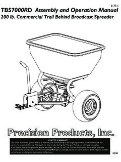
Transcription of TBS6000RD Trail Behind Broadcast Spreader
1 TBS6000RD . 2964-1. Trail Behind Broadcast Spreader Assembly Instructions & Parts List 04/04. MADE IN. USA. PRECISION PRODUCTS, INC. ASSEMBLY INSTRUCTIONS FOR THE TBS6000RD . ASSEMBLY TIP: Loosely tighten nuts and bolts at first. Fully tighten when the Spreader is completely assembled. Step 1. Attach the Tow Bar (3) to the center hole on the Cross Brace (6) using a 1/4 x 1-1/2 Hex Head Bolt (14) and a 1/4 Lock Nut (20). The Gear Case 1/4 x 1-1/2. Bracket (37) is attached on top of Hex Head Bolt the Tow Bar (3) and the Cross Brace (6).
2 Cross Brace Gear Case Bracket Tow Bar 1/4 Lock Nut Tow Bar Step 2. Wrap Attach the two Support Brackets (7) to Around the Wrap Around Support (4) using Support 1/4 x 1-1/2 Hex Head Bolts (14) and 1/4 Lock Nuts (20). Attach the other end of the two 1/4 x 1-1/2. Hex Head Support Brackets (7) to the Tow Bar (3) Bolt using a 1/4 x 2 Hex Head Bolt (13) and 1/4 Lock Nut (20). Support Tow Bracket Bar Support Bracket 1/4 x 2. Hex Head Bolt 1/4 Lock Nut Step 3 1/4 x 2-1/4 Control Carriage Bolt Cable Attach the Control Cable Holder (5) to the top of the Tow Bar (3) using 1/4 x 2-1/4.
3 Hex Head Bolts (12) and 1/4 Lock Nuts (20). Attach the two Clevis Plates (25) to the top and bottom of the Tow Bar (3) using 1/4 x 1-1/2 7/8 Tube Plug 1/4 Wing Nut Hex Head Bolts (14) and 1/4 Lock Nuts (20). Insert the 1/2 x 1-3/4 Clevis Pin (39) through the holes in Clevis Plates (25). Secure this with a #14 Hitch Pin Clip (34). Attach the Control Control Cable Holder Cable (8) to the top of the Control Cable Holder (5). using a 1/4 x 2-1/4 Carriage Bolt (11) and 1/4 Wing 1/4 x 2-1/4. Nut (23). Using a hammer, gently tap the two Hex Head Bolt 7/8 Tube Plugs (24) into the open ends of the 1/4 x 1-1/2.
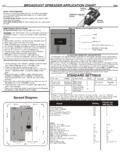
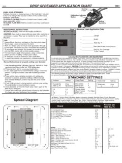
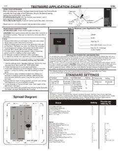
4 Control Cable Holder (5). x 1-3/4 Hex Head Bolt Clevis Pin Clevis Plates #14 Hitch Pin Clip 1/4 Lock Nuts Step 4. To ensure proper function of the gear case, make sure the Spinner Shaft is perpendicular to the bottom of the Hopper. Adjustments can be made with the Eye Bolt that connects the Gear Case Bracket to the Gear Case Housing. Eye Bolt USING YOUR SPREADERS CONTROLLER. Settings are made by pushing down on the Calibration Indicator Control Lever button and setting to the desired number on the Control Cable assembly.
5 Calibration SEE APPLICATION CHART FOR SETTING INFORMATION. Indicator button ON -- Push the Control Lever forward until it stops against Calibration Button. OFF -- Pull Control Lever back until it stops. Numbered Settings Broadcast Spreader OPERATION. 1. Always have the control lever in OFF position 4. Pull the Spreader at a steady speed (approximately before filling the hopper. 3 - 4 mph is recommended). 2. Always pull the Spreader forward to operate; 5. To avoid misses or striping, space each pass across the do not operate in reverse.
6 Lawn so approximately 20% of the spread width overlaps 3. Start moving forward before pushing the control onto the previous pass. This provides a feathered over- lever to the ON position. Pull the control lever to lap to even out distribution over the width of the spread. OFF position before stopping or turning. CAUTION: care must be taken with any weed killer, DO NOT allow Spreader to sit stationary with pesticide, or combination product. They can be harmful material in the hopper and control lever in the to other plant life in the yard.
7 ON position.. Recommended operating weight 120 lbs. MAINTENANCE INSTRUCTIONS. 1. Empty hopper after each use. Do not store Spreader LIMITED WARRANTY. with material left in hopper. This unit is warranted against defects in materials and workmanship to the 2. Wash Spreader thoroughly and wipe dry. original purchaser, under normal use and service, for a period of ninety (90). 3. Lubricate all moving parts. Use a grease gun to apply days from date of sale. During the Warranty Period, we will repair or replace grease to the gearbox assembly.
8 CAUTION: Use a at our option free of charge to the original purchaser, any part of the Unit reasonable amount of grease. DO NOT pack that our examination shows to be defective in workmanship or materials. gearbox full of grease. Apply oil to spinner shaft This Warranty Does Not apply to damage caused by transit, misuse, abuse, (including area shaft extends through hopper), slide neglect, accident, normal wear, or alterations by unauthorized persons. plate and where the spinner shaft and axle extend through the gearbox.
9 10 11 12 13 14 15 16 17. 1 50 18. 19. 20 21 22 23. 2 24. 25. 26 27 28 29 30 31. 3. 6 32. 4 33 34 35 36. 5 9. 37 39 51. 7 38. Gear Case Components 8 40. HOW TO ORDER. REPLACEMENT PARTS: 16. 32. PLEASE DO NOT RETURN When ordering parts always give model number, part 29 41. THIS MERCHANDISE TO THE 42. number and part description. STORE. CALL US AND WE 43. 44 45. WILL TAKE CARE OF ANY 46. Send To: Parts Division PROBLEM YOU MIGHT HAVE 316 Limit Street WITH THIS PRODUCT. Lincoln, IL 62656 44. Phone (800) 225 - 5891 47 43.
10 EXT. #204 Phone (800) 225-5891. (217) 735-1590 Ext. 204 48. FAX (217) 735-2435 49. Ref Parts Description Qty Ref Parts Description Qty No No No No 1 2969 Hopper 1 27 6143 1/4 Fender Washer 4. 2 INSET Gear Case Assembly ** 28 6127 1/4 Rubber Washer 4. 3 7185G Tow Bar 1 29 1807 1/4 Lock Washer 1. 4 7156G Wrap Around Support 1 30 2987 3/16 Lock Washer 1. 5 7182G Control Cable Holder 1 31 1008 1/2 Retaining Ring 1. 6 7126G Cross Brace 1 32 2983 1/4 Grease Zerk 1. 7 2928G Support Bracket 2 33 2905 Agitator Pin 1. 8 2438 Control Cable 1 34 1042 #14 Hitch Pin Clip 1.