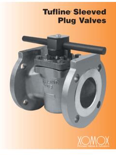
Transcription of Tech Sheet - 76-100 Series
1 A-9 COPYRIGHT 2008 CONBRACO IND., INC. PRINTED IN SeriesStainless Steel Ball ValveT h readed, 1/4 to 1 2000 psig WOG, 1-1/4 to 2 1500 psig WOG, 2-1/2 to 3 1000 psig WOG. (See re f e renced P/T chart )Cold Non-Shock. 150 psig Saturated Steam, Vacuum Service to 29 inches Specification: WW-V-35C, Type: II, Composition: SS, Style: SP-110; Ball valves Threaded, Socket-Welding, Solder Joint, Grooved and Flared Investment cast components Adjustable packing gland RPTFE seats and stuffing box ring Meets NACE MR-01-75 Mounting pad for easy actuator mounting SS lever and nut Blow-out-proof stem design (-24) 1/4 to 2 Certified to API 607,4th Edition, Class 600 burnSTANDARD MATERIAL LIST1.
2 Lever and grip304 SS w/vinyl7. Gland nutA276-3162. Stem packingRPTFE8. StemA276-3163. Stem bearingRPTFE9. Lever nut18-8 SS4. BallA276-31610. Body sealPTFE5. Seat (2)RPTFE11. Body A351-CF8M6. RetainerA351-CF8 MOPTIONS AVAILABLE:( S U F F I X )O P T I O NS I Z E S- 0 2 -Stem Gro u n d e d1/4 to 3 - 0 3 -1-1/4 CS Stem Extension1/4 to 3 - 0 4 -2-1/4 CS Stem Extension1/4 to 3 - 0 7 -Steel Tee Handle1/4 to 2 - 0 8 -90 Reversed Stem1/4 to 3 - 1 4 -Side Vented Ball (Uni-Dire c t i o n a l )1/4 to 2 - 1 5 -Wheel Handle, Steel1/4 to 2 - 1 6 -Chain Lever - Ve r tical 3/4 to 2 - 1 9 -Lock Plate1/4 to 2 - 2 1 -UHMWPE Trim (Non-PTFE)
3 1/4 to 3 - 2 4 -Graphite Packing1/4 to 3 - 2 7 -SS Latch-Lock Lever & Nut1/4 to 3 - 3 0 -Cam-Lock and Gro u n d e d1/4 to 2 - 3 2 -SS Tee Handle & Nut1/4 to 2 - 3 5 -VTFE Tr i m1/4 to 3 - 3 9 -SS Hi-Rise Locking Wheel Handle, SS Nut1/4 to 2 - 4 0 -Cyl-Loc and Gro u n d e d1/4 to 2 - 4 4 -Seal We l d e d1/4 to 2 - 4 5 -Less Lever & Nut1/4 to 3 - 4 6 -Latch Lock Lever - Lock in Closed Position Only 1/4 to 3 - 4 7 -SS Latch Lock Oval Handle1/4 to 1 - 4 8 -SS Oval Handle (No Latch) & Nut1/4 to 2 - 4 9 -Assembled Dry1/4 to 3 - 5 0 -2-1/4 CS Locking Stem Extension1/4 to 3 - 5 7 -Oxygen Cleaned1/4 to 3 - 5 8 -Chain Lever - Horizontal3/4 to 2 - 6 0 -Static Grounded Ball & Stem1/4 to 3 - 6 4 -250# Steam Tr i m1/4 to 3 - P 0 1 -BSPP (Parallel) Thread Connection1/4 to 3 - T 0 1 -BSPT (Ta p e red) Thread Connection1/4 to 3.
4 STEEL BALL VALVEFor Pressure/Temperature Ratings,Refer to Page M-12, Graph No. 14(1/4 to 1 )Refer to Page M-11, Graph No. 12(1-1/4 to 2 )Refer to Page M-10, Graph No. 8(2-1/2 to 3 )M-12 COPYRIGHT 2008 CONBRACO IND., INC. PRINTED IN 2008 CONBRACO IND., INC. PRINTED IN 2008 CONBRACO IND., INC. PRINTED IN 2008 CONBRACO IND., INC. PRINTED IN DATAFor apollo and Saturn Ball ValvesThe listed Cv factors are derived from actual flow testing, in the apollo Ball Valve Division, ConbracoIndustries, Inc., Pageland, South Carolina. These tests were completed using standard off the shelf valves withno special preparation and utilizing standard schedule 40 pipe.
5 It should be understood that these factors are forthe valve only and also include the connection configuration. The flow testing is done utilizing water as a fluidmedia and is a direct statement of the gallons of water flowed per minute with a 1 psig pressure differentialacross the valve/connection unit. Line pressure is not a factor. Because the Cv is a factor, the formula can beused to estimate flow of most media for valve 3/8 1/2 3/4 1 1-1/4 1-1/2 2 2-1/2 3 4 OPEN90 FACTORSSERIES:70-100, 71-100, 71AR, 73A-100,74-100, 76-100 , 80-10081-100, 89-100 Flow of LiquidQ =Cv PSpGror P =(Q)2(SpGr)(Cv)2 Flow of GasQ = 1360 Cv ( P)(P1)(SpGr)(T)or P = x 10- 7(SpGr)Where :Q = flow in SCFH P = pressure drop(psi g)SpGr =specific gravity(based on ai r = )P1= outletpres sure psia(psig + )T = (temp.)
6 F + 460)Where:Q = flow in US gpm P = press ure drop(ps ig)SpGr = specific gravity atfl owing tempera-tureCv = valve constantSIZE1/4 3/8 1/2 3/4 1 1-1/4 1-1/2 2 2-1/2 3 4 OPEN90 FACTORS82-100/200, 83R-100/200/700,86R-100/200/700,83-500/6 00,86-500/600/900 SERIESCv FACTORS76F,77,77AR,77D SERIESSIZE1/4 3/8 1/2 3/4 1 1-1/4 1-1/2 2 2-1/2 OPEN90 3/8 1/2 3/4 1 1-1/4 1-1/2 2 OPEN90 FACTORS83A/83B, 86A/86B Series