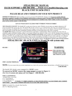
Transcription of TECH SUPPORT 1-888-588-4506 ….WEB …
1 1 stealth I DC MANUAL tech SUPPORT 1-888-588-4506 ..WEB black unit IS 24/36 ONLY PLEASE READ AND UNDERSTAND YOUR NEW PRODUCT IMPORTANT MESSAGE: Before installing your newly purchased stealth I DC charging system be sure to read the following instructions completely, regardless of your familiarity with electricity or electrical systems. You must follow the instructions contained in this manual. This unit is an electrical component and can be damaged when installed wrong. If after reading, you have any questions please call our toll free tech SUPPORT number ( 1-888-588-4506 ). ALWAYS WEAR SAFETY GLASSES WHEN WORKING WITH BATTERIES! THE stealth I CONCEPT: The stealth I DC accepts power from any source.
2 Whether you are using your engines alternator or AC power the stealth I DC operates the same. The stealth I DC and AC connects to your cranking battery and when your cranking battery reaches full charge, the stealth I DC turns on and steps up the voltage to your trolling motor or aux. batteries. With the stealth I volt meter in place and properly used the full battery maintenance program will keep you from going dead on the water as designed. The stealth I DC charging system gets it s power directly from your engine s cranking battery. When in operation, the state-of-the-art technology applies on-demand charging voltage to your marine trolling or aux. batteries so they receive only the charging current required to replace energy that has been consumed.
3 The stealth I Smart Charging Circuit Design works to ensure your cranking battery voltage will not fall below , thus, providing plenty of stand-by power to start your engine. The stealth I DC also works to prevent over-charging of your trolling or aux. batteries by monitoring output voltage and then automatically switching to a float mode to maintain optimum charging. The life of the batteries will be longer due to the charging method.( See Question & Answers at the end of the manual.) stealth I DC ( black unit ) is 24 and 36 volt system only WARNING FIGURE 1 POS ** POS POS STEP 1: RANGE TERMINALS NOTE: If you are unsure what your system requirements are, check with your local marina, boat mechanic, or stealth Customer Service.
4 The stealth I DC already comes equipped for a 24 VDC system. (Jumper on seen above) ( 1-888-588-4506 ) To convert to 36 VDC remove the range jumper seen in (figure 1 step 1) (For 12 to 12 systems only) please call tech SUPPORT 1-888-588-4506 STEP 2 : COMPONENTS (4) Nylon Spacers (4) Mounting Screw (1) Wiring Harness .. 1 - RED 4 power-in; 2 YELLOW 4 ground (crank neg.) and A 6 ground neg crank to neg trolling; 1 - ORANGE 6 trolling power-out (4) 3 Mounting Screws : with the stealth I Pro or stealth I Max Pack Pro ORANGE .. 24 or 36 VDC POSITIVE TROLLING BATTERY POST.
5 POWER-OUT (X) 2 THESE ARE JOINED TOGETHER FOR ONE OUTPUT SETUPS TO EQUALY SHARE DUTY CYCLE THIS unit HAS ONE GROUND (YELLOW) CRANK NEGATIVE THE OTHER CONNECTORS ARE POSITIVE LEADS RED .. 12 VDC POSITIVE CRANK POWER-IN 2 **NOTE ** WHEN LOOKING AT THE NOTICE ALL BATTERIES ARE COMMON GROUNDED .. THE MOST COMMON MISTAKE IS LEAVING THE GROUNDS OFF. TOOLS REQUIRED FOR INSTALLATION Drill Phillips Screw Driver 3/8 and 5/16 Nut Driver Volt Meter (May Be Required) makes finding the 24 and 36 volt positive leads easiest. STEP 3 : INSTALLATION (FOR 12 TO 12 OR 48 VOLT INSTALLATION PLEASE CALL 1-888-588-4506 ) 1. Mount the stealth I DC in an area that is least likely to be flooded or submerged.
6 BE SURE and insert the one-quarter inch (1/4 ) nylon spacers between the bottom of the stealth I DC and the mounting surface as seen in (Figure 2 below), unless mounted with the stealth I AC as seen in (Figure 3) with (3 ) mounting screws. A vertical mounting position is preferred for both installs (Figure 2). NOTE: The AC unit is generally mounted behind the DC unit . The AC is molded with 2 spacer tracks for mounting the DC on top of the AC, but it can be separated if space is limited or the DC was the only unit purchased as in figure 1. Figure 2 DC unit ONLY. Figure 3 AC and DC piggyback DC unit 3 !
7 /2 mounting screw holes IMPORTANT REMINDERS: AC unit GROUNDS CONNECTED PROPERLY: Be sure the charger ground YELLOW is connected to the crank battery negative post and the power input RED is to the positive post of the crank battery. And the other batteries must be common grounded with the 10 gauge YELLOW 7 cable included in the wiring harness. (See the grounds in the option pages 3-5) DC LED LIGHT: When the green LED light is on, it indicates that the stealth I DC is powered and monitoring the batteries as designed. MAINTENANCE: The breaker terminals and connections should be covered with white/clear grease or corrosion x (or a similar product), which protects against oxidation and corrosion.
8 BATTERY MAINTENANCE: Periodically checking your trolling batteries is essential for achieving maximum performance from your batteries. At least once a month you should check your battery acid levels and follow your manufacturer s instructions for replenishing the same (For example, if electrolytes are low, you may add distilled water to some batteries if approved by the manufacturer). You should also periodically check your batteries for voltage and look for differences in voltage between your batteries. If there is more than a 2 VDC difference between batteries after charging, the affected battery should be professionally tested and/or replaced. THE stealth I DIGITAL GAUGE COMPLETES THE FULL BATTERY MAINTENANCE PROGRAM stealth WAS DESIGNED TO BE.
9 FOR INFO ON THE GAUGE CALL 888-588-4506. AC lights will go solid green when finished 3 ORANGE OUTPUT GOES TO 24 POS. POST YELLOW OR black COMMON GROUND (NEG CRANK TO NEG TROLLING) GOES TO 24 VOLT NEG (NEG. & POS. THAT DOES NOT HAVE THE JUMPER IS 24 VDC CONNECTIONS) OPTION #1 24 VOLT SYSTEM WITH AC Breakers are manual reset only: Red & Yellow = 50amp Orange output = 20 amp IF YOU ARE NOT SURE CALL tech SUPPORT 888-588-4506 OPTION #2 36 VOLT SYSTEM WITH AC YELLOW or black common ground YELLOW or black The 2 post without a jumper connected on the Batteries are your 36 VDC leads The range jumper should be in place for 24 volts The Range Jumper should be removed for 36 volts ALL WIRE 10 GAUGE OR BIGGER NOTE 1ST STEP IF THE BATTERIES ARE NOT JUMPED AS SEEN.
10 YOUR BATTERIES ARE JUMPED IN THE PLUG. YOU DO NOT HAVE TO ADD A JUMPER !!! USE A VOLT METER TO FIND THE 24-VOLT POSITIVE AND NEGATIVE. TAKE THE METER POS. PROBE TO BAT 2 POS. AND THE NEG. PROBE TO THE 1st BAT NEG. POST. IF THE READING IS NOT YOUR 24 VOLTS THEN REPEAT (ABOVE) AND CHANGE POSITIVE TO BAT 1 NEGATIVE TO BAT 2 If there is one crank battery both leads go to the crank from the AC If there is one crank battery both leads go to the crank from the AC. Reds pos Blacks neg REDYELLOW REDORANGE ORANGE 4 OPTION #3 36 VOLT SYSTEM CRANK as TROLLING WITH AC Series Jumper NEG to POS not a common ground here YELLOW OR black OPTION #4 24 VOLT SYSTEM CRANK as TROLLING WITH AC Series Jumper NEG to POS not a common ground here TROLLING MOTOR NEG.