Transcription of TechBook - Gecko Alliance Group
1 Y seriesTMwhatever the spa, this is your control systemTotal Flexibility Total Compatibility Total SatisfactionTechBookGecko Alliance450 des Canetons, Quebec City (Qc), G2E 5W6 Canada, Stellar Court, Corona, CA 92883 USA, in Canada 08-2012 9919-101184 Rev. 08-2012 Groupe Gecko Alliance Inc., 2012 All trademarks or registered trademarks are the property of their respective Series TechBook11 Table of contentsWarnings 2 Introduction 3 Features 4in ye overview: 5in ye dimensions: 5in yt overview: 6in yt dimensions: 6in k200 dimensions: 7Y Series installationin k200 installation & connections -Installing the in k200 9 -Connecting the main keypad to the spa pack 9Y Series connections -Electrical wiring for North American model of the Y Series 10 -Electrical wiring for North American or CE model of the Y Series 10 -Heater connections 12 Power-up & breaker setting 13 Programming the Y Series 14 Low-level configuration selection charts 15Y Series field programming options 18 -High voltage accessory connections 21In k200 keypad overview -Function description 26 -Instructions 26 -Typical settings 28Y Series error codes -Y Series error codes summary 29 -Hr error message / flow chart & step-by-step 30 -Prr error message / flow chart & step-by-step 30 -HL error message / flow chart & step-by-step 31 -FLO & UPL error message / flow chart & step-by-step 33 -OH error message / flow chart & step-by-step 34 Troubleshooting -Pump 1 doesn't work
2 / flow chart & step-by-step 35 -Pump 2 or blower doesn't work / flow chart & step-by-step 37 -Circulation pump doesn't work / flow chart & step-by-step 39 -Ozonator doesn't work / flow chart & step-by-step 40 -Nothing seems to work / flow chart & step-by-step 41 -Nothing seems to work / flow chart & step-by-step 42 -Spa not heating / flow chart & step-by-step 44 -Keypad doesn't seem to work step-by-step 45 GFCI trips 45 Step-by-step field replacement procedure 46 How to replace the heater 49 How to replace main control board on in ye 50 How to replace the main control board on in yt 51 How to replace the upper extension board on the in yt 52 Specifications 532Y Series TechBook WARNINGS: Before installing or connecting the unit, please read the following * FOR UNITS FOR USE IN OTHER THAN SINGLE-FAMILY DWELLINGS, A CLEARLY LABELED EMERGENCY SWITCH SHALL BE PROVIDED AS PART OF THE INSTALLATION THE SWITCH SHALL BE READILY ACCESSIBLE TO THE OCCUPANTS AND SHALL BE INSTALLED AT LEAST 5' (1 52 M)
3 AWAY, ADJACENT TO, AND WITHIN SIGHT OF THE UNIT * ANY DAMAGED CABLE MUST BE IMMEDIATELY REPLACED * TURN POWER OFF BEFORE SERVICING OR MODIFYING ANY CABLE CONNECTIONS IN THIS UNIT * TO PREVENT ELECTRIC SHOCK HAZARD AND/OR WATER DAMAGE TO THIS CONTROL, ALL UNUSED BUSHING CONDUITS MUST BE PLUGGED WITH THE ATTACHED NIPPLE * THIS CONTROLLER MUST NOT BE INSTALLED IN PROXIMITY OF HIGHLY FLAMMABLE MATERIALS * LOW SUPPLY VOLTAGE OR IMPROPER WIRING MAY CAUSE DAMAGE TO THIS CONTROL SYSTEM READ AND FOLLOW ALL WIRING INSTRUCTIONS WHEN CONNECTING TO POWER SUPPLY * THIS PACK CONTAINS NO USER SERVICEABLE PARTS CONTACT AN AUTHORIZED SERVICE CENTER FOR SERVICE * ALL CONNECTIONS MUST BE MADE BY A QUALIFIED ELECTRICIAN IN ACCORDANCE WITH THE NATIONAL ELECTRICAL CODE AND ANY STATE, PROVINCE OR LOCAL ELECTRICAL CODE IN EFFECT AT THE TIME OF THE INSTALLATION Aeware , Gecko , and their respective logos are Registered Trademarks of Gecko Alliance Group In yt , in ye , in keys , in touch , in k200 , in flo , in put , in seal , in link , in t cip , in stik , heat wav , Y Series , and their respective logos are Trademarks of Gecko Alliance Group All other product or company names that may be mentioned in this publication are tradenames, trademarks or registered trademarks of their respective owners WarningsY Series TechBook3 IntroductionY Serieswhatever the spa, this is your control systemThis product is the simplest, most flexible solution when it comes to supporting even the most complex array of spa add-ons and options The Y Series offers the kind of simplicity that makes for a genuine top-of-its-class product It is the natural choice for anyone who wants an easy-to-understand multi-application solution With the Gecko Y Series you don't have to wonder about compatibility.
4 Instead, there s just the comforting certainty that when you invest in the Y Series, all spa configurations are supported What's more, it also takes into account future compatibility, so you can enjoy peace of mind knowing that you can enjoy the Y Series for years to come 4Y Series TechBookIn put was designed to ease wire insertion (up to # 4 AWG) and connections Tighter input connection reduces heat generated for increased component lifetime input terminal block In seal provides an extra level of protection against water infiltration Connectors and power box are designed to be watertight so that no water can be in direct contact with electrical components (IPX5) protectionA heater safety system located on the heat wav heater with an all-electronic dry-fire protection protectIn t cip is an intelligent water temperature refresh algorithm that calculates optimal time to start pumps and get water temperature readings In t cip continuously readjusts the heater start time temperature algorithmFeaturesThe Y Series systems boast a long list of technical features Each of them contributes to bringing the most advanced solutions available to Y Series equipped spa owners.
5 In stik is a pen drive with an in link connector very similar to a USB memory stick It connects to the spa pack and contains data to program or configure its system The system executes the data upload automatically software upload All Yseries packs support the in touch WiFi interface, allowing you to use your favorite iOS device to communicate with your spa 're always in touch with your relaxationThe Y Series is only compatible with the low-voltage family of in link connectors, such as those used by keypads and similar low-voltage accessories plugs and connectorsSpecificationsRefer to the detailed specification chart printed on page 54 Y Series dimensions:Main powerentry connectionheat wav heater with in flo technologyWatertight strainrelief systemAccess to heaterconnectionsMounting feetIndustry-standard AMPconnectors for outputsEnough outputs for allyour spa needsLight outputs(1 direct, 1 switched)Main keypad connectorCommunications link(in touch or in stik)Accessible bonding lugsFront viewSide view4 98"(126 mm)2"(51 mm)10 75"(273 mm)16 554"(420 mm)19 598"(498 mm)2 875 "(73 mm)10 473"(266 mm)1 625"(41 mm)2 605"(66 mm)Bottom view4 563"(115 mm)2 25"(57 mm)4 285"(108 mm)7 160"(182 mm)Rear view17"(431 mm)Note: Shown with optional wall mouting Series dimensions.
6 Main powerentry connectionheat wav heater with in flo technologyWatertight strainrelief systemAccess to heaterconnectionsMounting feetIndustry-standard AMPconnectors for outputsCommunications link(in touch or in stik)Enough outputs for allyour spa needsLight outputs(1 direct, 1 switched)Main keypad connectorCommunications link(in touch or in stik)Accessible bonding lugsFront viewSide view5 16"(130 mm)2"(51 mm)14 5"(368 mm)Bottom view16 62"(422 mm)19 60"(498 mm)2 88"(73 mm)10 47"(266 mm)1 63"(41 mm)2 61"(66 mm)11 0"(279 mm)4 29"(109 mm)2 04"(52 mm)8 09"(205 mm)10 96"(278 mm)Rear view16 90"(429 mm)Note: Shown with optional wall mounting Series TechBook7 The following material is recommended:4- # 10 screws of appropriate length with round, truss or pan head 4- washers 1/2" OD x 1/16" thickness (12 mm OD x1 5 mm)Select the most appropria-te location on the floor for spa pack and firmly attach guide plate to wooden base with 2 screws backed by 2 washers dimensions:2"(51 mm)4 75"(120 mm)1 7"(43 mm)Now firmly attach unit to wooden base by using the remaining 2 screws backed by 2 washers to attach the front feet Features: LED display 4 keys 8 light indicator in link connectorMechanical Specs:Weight: 0 9 lbs (0 41 kg)Dimensions (W x H x D): Front panel: 4 75" x 2" x 1 7" (120 mm x 51 mm x 43 mm) Soft gasketApprovals: UV resistance (ASMTD4329) UL, CSA, TUV and CENote: The spa pack must be installed at least 4" (52 mm) above potential flood level.
7 If floor is on ground level, pack should be raised at least 4" (52 mm). Slide back side of the unit's feet into the guide plate It should easily slide into place 4"Floor installation procedure with optional guide plateY Series installation Warning! Beware the application of some products commonly used against corrosion (such as WD-40 family products) as they could damage the power box, due to a negative chemical reaction between some industrial oils and its plastic enclosure Any other materials which may come in contact with the enclosure must be carefully evaluated under end use conditions for compatibility Important! Please note that countersunk screws should not be used as they can damage the power box support 8Y Series TechBookThe following material is recommended:4- # 10 screws of appropriate length with round, truss or pan head 4- washers 1/2 OD x 1/16 thickness (12 mm OD x1 5 mm)Select the most appropriate location on the floor for the spa pack and firmly attach the 2 rear feet to the wooden base using 2 screws backed by 2 washers Note: The spa pack must be installed at least 4" (52 mm) above potential flood level.
8 If floor is on ground level, pack should be raised at least 4" (52 mm).Important! Please note that countersunk screws should not be used as they can damage the power box support Now firmly attach the front feet of the pack to the wooden floor using 2 more screws backed by 2 washers 4"Floor installation procedure without guide plate Warning! Beware the application of some products commonly used against corrosion (such as WD-40 family products) as they could damage the power box, due to a negative chemical reaction between some industrial oils and its plastic enclosure Any other materials which may come in contact with the enclosure must be carefully evaluated under end use conditions for compatibility The following material is recommended:4- # 10 screws of appropriate length with round, truss or panhead 4- washers 1/2" OD x 1/16 thickness (12 mm OD x 1 5 mm)Use 2 standard 2x4 or 2x6 wall studs, spaced on 17-inch centers to affix the spa pack Firmly attach lower mounting holes on each side of the pack with the 2 remaining screws and 2 washers Lower mounting holes are 2" (51mm) below upper holes Firmly attach, one at a time, upper mounting holes on each side of the spa pack with 2 screws backed by 2 washers Install mounting brackets on both sides of rear of unit, using the screws provided with the bracket Wall installation procedure with optional wall mounting bracketsY Series TechBook9 Installing the keypad should be installed directly onto the spa (or very close to it) so that it is easily accessible to the user To install the in k200, drill two 1 (25 mm) diameter holes at 2 5/8 (67 mm) from center to center as illustrated Cut out the material between the two holes (see illustration)
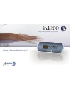
9 Clean the installation surface and peel the adhesive backing from the keypad Insert keypad and align it correctly, then ensure it is properly glued by gently pressing evenly on the entire surface If the keypad is equipped with an optional holder plate, remove the two wing nuts from the back of the keypad and remove the mounting bracket Insert the keypad into the opening you have cut out Put the mounting bracket and the wing nuts back on their respective bolts and fix the keypad securely in place (see illustration below) Note: It is the installer s responsibility to ensure that no obstructions (cables, piping, etc.) are present below the deck at the drill hole : If the installation location is not perfectly even ( wood surface), make a silicone joint between the installation surface and the back of the unit to ensure a proper seal around it. 1"(25 mm)Gasket with adhesive2 5/8"67 mm 1"(25 mm) 1"(25 mm)1" (25 mm) dia drill1"(25 mm)3 5/8"92 mmConnecting the main keypad to the spa packThe in k200 comes with a 10' (3 048 m) cable and an in link connector To connect the in k200, first remove the cover (for in ye 4 screws and for in yt 6 screws), then insert the in link connector into the appropriate keypad connector (as illustrated) Route the cable through one of the molded strain relief channels on the bottom right side of the spa pack (as illustrated) Don t forget to replace the cover and all screws (do not over tighten cover screws) Note: always shut power down before connecting an accessory to the or k200 Connect the main keypad in k200 as indicated here installation & connections10Y Series TechBookElectrical wiring for North American model of the Y SeriesElectrical wiring for North American or CE model of the Y SeriesMain electrical boxGFCI panel Warning!
10 For units for use in other than single-family dwellings, a clearly labeled emergency switch shall be provided as part of the installation The switch shall be readily accessible to the occupants and shall be installed at least 5' (1 52 m) away, adjacent to, and within sight of the unit ----- This product must always be connected to a circuit protected by a ground fault interrupter Proper wiring of the electrical service box, GFCI and in yt terminal block is essential! Check your electrical code for local regulations Only copper wire should be used, never aluminum ----- Disposal of the product The appliance (or the product) must be disposed of separately in accordance with the local waste disposal legislation in force To install the wiring for the Y Series spa control, you'll need a Phillips screwdriver and a flat screwdriver Loosen the 4 or 6 screws of the spa pack cover and remove it Remove 5 1/2" (142 mm) of cable insulation Strip away 1" (25 mm) of each wire insulation Pull the cable through the cutout of the box and secure it with a strain relief (1" NPT strain relief.)


