Transcription of Technical Bulletin CORE LOSS TESTING THEORY
1 core loss TESTING IN THE PRACTICAL MOTOR REPAIR ENVIRONMENT ABSTRACT LEXSECO developed the first commercial core loss Tester over thirty five years ago. Since inception, LEXSCO has performed core loss tests in a variety motor repair shop environments. Thousands of LEXSECO testers are in use around the world. This publication will present the mathematical foundations of the toroidal transformer type core loss test and discuss the application of this test procedure to the motor repair environment including common core repair techniques. Technical Bulletin core loss TESTING THEORY INTRODUCTION TO LOSSES Before any test procedure for determining core losses and core degradation can be explained, the nature of steel properties should be understood.
2 Ferrous materials have various electrical, magnetic and mechanical properties that are taken into consideration during the design of an electrical apparatus. The object of the design is typically to maximize output while minimizing the associated electrical and mechanical losses. By design, the motor is known to have a certain level of I2R copper loss , windage and friction, and stray load losses which accompany the specific design parameters of the motor. Similarly designers choose the grade of core steel, the designed thickness of the steel and the processing techniques in an attempt to minimize the steel losses without incurring a substantial increase in material costs.
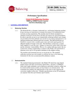
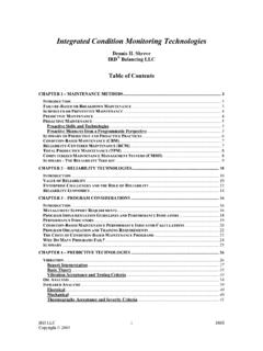
3 These losses are divided into two categories: current lossesFigure 1 - Hysteresis loss Curve Hysteresis loss is the amount of input energy expended to change the magnetic polarity of the steel in conjunction with the changing polarity of the alternating current waveform. This portion of the total core loss is represented by the shaded portion of the hysteresis curve shown in Figure 1. Ideally, the voltage (VS) to magnetization current (IM) graph would be represented by a single path from A to B equal to the path from B to A. However, due to this increase in expended energy, the path from A to B is not equal to the path from B to A, and a hysteresis loop is developed.
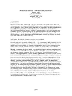
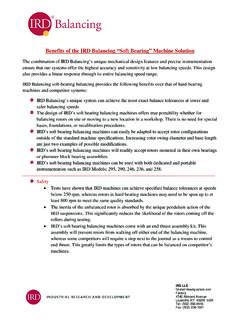
4 The area between the two paths is identically equal to the hysteresis loss . Hysteresis loss will be dissipated in the form of heat. Eddy currents are circulating currents resulting from the magnetic fields generated in the electric motor. Normal eddy current flow is shown in Figure 2. Figure 2 - Normal Eddy Current Flow When any electrical conductor is placed within a magnetic field, a current proportional to the cross-section of the conductor and the strength of the field is known to flow perpendicular to that field. For this reason, steel lamination thickness is minimized to reduce the amount of Technical Bulletin core loss TESTING THEORY eddy current flow.
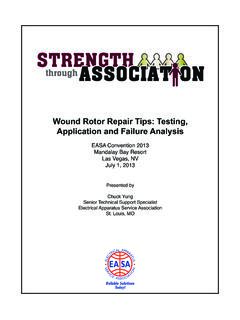
5 When the insulation between laminations breaks down, there is an associated increase in the eddy current flow. At the point of degradation, currents flow between the laminations as shown in Figure 3. Eddy current loss is the total input power lost to these circulating currents. Like hysteresis loss , eddy current losses are dissipated in the form of heat. Figure 3 - Interlaminar Eddy Current Flow Summing the eddy current and hysteresis losses will provide the total core losses for any given motor. core loss TEST PROCEDURES Today, there exists two types of tests for determining the total core loss of an electric motor.
6 The first of these is known as the segregated loss method described in the Institute of Electrical and Electronics Engineers (IEEE) Standard 112 and the Canadian Standards Association Standard 390. Using linear regression analysis and various percentage loading characteristics, this test method determines each component of the total losses as well as the subject motor efficiency. When the exact nature of core losses in the complete motor system are required, this type of test is much more effective than any other test of its type.
7 However, the subject motor must be in complete working order. This limits its usage to motor repairs which can be classified as preventative maintenance repairs. Second, the TESTING procedure must be performed in laboratory controlled environments. Subletting core loss TESTING to laboratories specifically devoted to motor TESTING is a costly and time consuming venture. Conservative estimates of the time and cost of segregated loss TESTING is approximately one day per motor at upwards of $1000 per day. This further reduces the set of motors to non-emergency breakdowns.
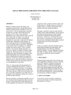
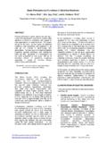
8 Obviously, for the motor repair industry, the segregated loss method for determining the condition of the core is very impractical. The other method, which is well suited to the motor repair industry, is commonly referred to as the Toroidal Transformer Test, or loop test, as shown in Figure 4. Figure 4 - Toroidal Transormer Test While there exist several variations on the toroidal transformer test procedure, they all share the same basic mathematical foundations. The principles underlying the traditional loop test, and the commercial core loss Tester, are based upon an electromagnetic equation known as Faraday s Law.
9 This application of Faraday s Law (1) holds that any laminated steel core assembly, regardless of size or design, can be used as the core of a toroidal transformer. Once excited to a selected backiron flux density, the power lost to the core steel can be measured. More specifically, (1) Where v is the induced voltage, n is the number of turns in the transformer and is the flux in the core . Given that (2) 2 Technical Bulletin core loss TESTING THEORY where BM is the flux density and c is the cross-sectional area of the toroid, we can directly incorporate the flux density (2) into Faraday s Equation (3).
10 (3) With the loop test, the voltage (v) in Faraday s Equation is held constant at the value supplied by the fixed power source. With a known target back iron flux density (BM), this equation can be solved for the number of turns (n). By wrapping the calculated number of turns around the core , the target flux density is achieved. Being both labor intensive and applicable to only stator cores, the loop test is often omitted from the repair procedure of most repair shops. For the commercial core loss tester, the number of turns (n) is held constant at one turn and the voltage source isvaried.