Transcription of TECHNICAL DATA DELUGE SYSTEM - vikingcorp.com
1 TECHNICAL DATAA pril 17, 2009 DELUGE SYSTEMThe Viking Corporation, 210 N Industrial Park Drive, Hastings MI 49058 Telephone: 269-945-9501 TECHNICAL Services 877-384-5464 Fax: 269-818-1680 Email: 201a1. DESCRIPTIONA DELUGE SYSTEM is a fixed fire-protection SYSTEM which totally floods an area with pressurized water through a SYSTEM of piping and open nozzles or sprinklers. The SYSTEM piping is empty until the DELUGE valve is activated by a hydraulic, pneumatic, electric or manual release APPLICATIONSR egular DELUGE systems may be required to protect extra-hazard occupancies by creating a fire buffer zone or by cooling surfaces to prevent deformation or structural collapse.
2 Examples: storage or process areas containing substances having a low flash point; areas in which fire may spread rapidly; tanks containing combustible solutions, transformers, equipment pits or product handling systems. Systems should be designed by qualified fire-protection engineers in conjunction with the approving bodies having DELUGE systems are those using foam-water sprinklers or spray nozzles and an air-foam concentrate which is introduced into the water at controlled rate on the SYSTEM side of the DELUGE valve. Foam water systems are used to control and/or extinguish fires which require a smothering and cooling agent. Examples: extraction plants, aircraft hangars and areas where flammable-liquid spill fires may OPERATIONThe Viking DELUGE valve prevents water from entering the SYSTEM piping until required.
3 The DELUGE valve is kept closed by a pressurized upper valve chamber. The pressure is maintained through a restriction on the service side. This upper chamber is also connect-ed to the release line. When the pressure is relieved from the upper chamber through the release line, the clapper is lifted by the water pressure under the clapper. Water floods the SYSTEM and rings alarm. For complete operation of individual Viking devices, see the applicable device pages in the Engineering and Design data INSPECTIONS, TESTS AND MAINTENANCER efer to NFPA 25 for Inspection, Testing and Maintenance AVAILAbILITYV iking DELUGE SYSTEM componenets are available through a network of domestic and international distributors.
4 See The Viking Corpo-ration web site for the closest distributor or contact The Viking GUARANTEEFor details of warranty, refer to Viking s current list price schedule or contact Viking page replaces page 201a-b, dated April 18, 2003. (Reformatted.)Form No. F_020589 Viking TECHNICAL data may be found on The Viking Corporation s Web site at Web site may include a more recent edition of this TECHNICAL data DATAA pril 17, 2009 DELUGE SYSTEMThe Viking Corporation, 210 N Industrial Park Drive, Hastings MI 49058 Telephone: 269-945-9501 TECHNICAL Services 877-384-5464 Fax: 269-818-1680 Email: 201bForm No. F_020589 Revised page replaces page 201a-b, dated April 18, 2003.
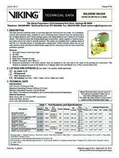
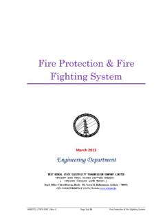
5 (Reformatted.)TAbLE 1 ItemDescriptionItemDescription1 Supply Main8 SYSTEM Piping2 Thrust Block9 Release SYSTEM Piping3 Riser to System10 Water Motor Alarm4 SYSTEM Main Drain and Flow Test Drain11 Emergency Release5OS&Y Supply Control Valve12 Spray Nozzles6 Emergency Release13 Thermostatic Release7 DELUGE Valve with Required Trim and Release EquipmentFigure 1